Cantilever Beam Bending Moment And Shear Force Diagrams
Muz Play
Mar 16, 2025 · 6 min read
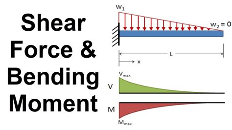
Table of Contents
Cantilever Beam Bending Moment and Shear Force Diagrams: A Comprehensive Guide
Understanding the behavior of cantilever beams under load is crucial for structural engineers and designers. Cantilever beams, fixed at one end and free at the other, exhibit unique stress distributions, making the accurate calculation of bending moments and shear forces paramount for ensuring structural integrity. This comprehensive guide will delve into the principles of calculating and interpreting bending moment and shear force diagrams for cantilever beams subjected to various loading conditions. We'll explore different load types, methods of calculation, and the significance of these diagrams in structural analysis.
What are Bending Moment and Shear Force?
Before we delve into cantilever beams specifically, let's clarify the concepts of bending moment and shear force. These internal forces are crucial in understanding the stress distribution within a beam.
Bending Moment (M)
The bending moment at a section of a beam represents the total moment of all forces acting on either side of that section. It's a measure of the bending action on the beam and is expressed in Newton-meters (Nm) or pound-feet (lb-ft). A positive bending moment typically indicates sagging (bending downwards), while a negative bending moment suggests hogging (bending upwards). This convention, however, might vary depending on the adopted sign convention.
Shear Force (V)
The shear force at a section is the algebraic sum of all vertical forces acting on either side of that section. It's a measure of the shearing action on the beam and is expressed in Newtons (N) or pounds (lb). A positive shear force generally indicates upward forces exceeding downward forces on the considered section. Again, consistent sign conventions are vital for accurate interpretation.
Calculating Shear Force and Bending Moment in Cantilever Beams
The process for calculating shear force and bending moment diagrams involves systematically considering each force and moment acting on the beam and their cumulative effect along its length. Here's a step-by-step approach:
-
Free Body Diagram (FBD): Start by drawing a clear free body diagram of the cantilever beam, showing all applied loads (point loads, uniformly distributed loads, uniformly varying loads, etc.) and the reaction forces at the fixed end. Remember that a cantilever beam has a fixed support which provides both a vertical reaction force and a moment reaction.
-
Sign Convention: Establish a consistent sign convention. A commonly used convention is:
- Positive Shear Force: Upward forces on the left side of a section or downward forces on the right side.
- Positive Bending Moment: Sagging (bending downwards)
-
Shear Force Calculation: For a given section along the beam, calculate the algebraic sum of the vertical forces to the left (or right) of that section. The shear force will be constant between concentrated loads, and will change linearly with the applied distributed load.
-
Bending Moment Calculation: Calculate the algebraic sum of the moments about the given section. Remember to consider the moment created by the shear force acting at a distance, and the moments from any applied moments. The bending moment is usually expressed as the area under the shear force curve.
-
Diagram Construction: Draw the shear force and bending moment diagrams, carefully plotting the calculated values against the beam's length. The diagrams should clearly show the magnitude and direction of the shear force and bending moment at different points along the beam.
Different Loading Conditions on Cantilever Beams
Cantilever beams can be subjected to various loading conditions, each producing distinct shear force and bending moment diagrams. Let's examine some common scenarios:
1. Point Load at the Free End
A point load (concentrated load) at the free end results in a constant shear force equal to the magnitude of the load throughout the beam's length. The bending moment varies linearly, reaching its maximum value at the fixed end.
- Shear Force Diagram: Constant value equal to the point load.
- Bending Moment Diagram: Linearly increasing from zero at the free end to the maximum at the fixed end.
2. Uniformly Distributed Load (UDL)
A uniformly distributed load (UDL) along the beam's length creates a shear force that varies linearly, starting from the value of the total load at the fixed end and decreasing to zero at the free end. The bending moment varies quadratically, with the maximum value at the fixed end.
- Shear Force Diagram: Linearly decreasing from the total load at the fixed end to zero at the free end.
- Bending Moment Diagram: Parabolic, reaching its maximum at the fixed end.
3. Uniformly Varying Load (UVL)
A uniformly varying load (UVL), where the load intensity changes linearly along the beam's length, yields a more complex shear force and bending moment diagram. The shear force varies quadratically, and the bending moment varies cubically.
- Shear Force Diagram: Quadratic variation.
- Bending Moment Diagram: Cubic variation.
4. Combination of Loads
Real-world cantilever beams often experience combinations of point loads, UDLs, and UVLs. To determine the shear force and bending moment diagrams for such cases, you must follow the superposition principle: Calculate the diagrams for each load individually and then algebraically add the results to obtain the overall diagram.
Interpreting Shear Force and Bending Moment Diagrams
The shear force and bending moment diagrams provide valuable insights into the beam's internal forces and are essential for:
-
Identifying critical sections: The diagrams reveal the locations where the shear force and bending moment are maximum, helping to identify critical sections that require special attention in design.
-
Determining maximum stresses: The maximum shear force and bending moment values are used to calculate the maximum shear stress and bending stress in the beam. These stresses are then compared with allowable stresses for the chosen material to ensure safety.
-
Beam design and selection: The diagrams are integral to the selection of appropriate beam size and material to withstand the expected loads.
-
Structural integrity assessment: Analysis of the diagrams allows for assessing the structural integrity of existing cantilever beams and identifying potential failure points.
Advanced Considerations
Several advanced factors can influence the shear force and bending moment diagrams:
-
Material Properties: The material's elastic modulus and yield strength affect the beam's response to the applied loads, influencing the stress distribution.
-
Beam Geometry: The beam's cross-sectional shape and dimensions significantly impact the moments of inertia and thus the bending stresses.
-
Support Conditions: Variations in support conditions, such as partial fixity or elastic supports, can alter the reaction forces and consequently the shear force and bending moment diagrams.
-
Dynamic Loads: In many real-world scenarios, cantilever beams are subjected to dynamic loads, such as vibrations or impact forces. Dynamic analysis is often necessary to determine accurate shear force and bending moment distributions in these cases.
Conclusion
The accurate calculation and interpretation of shear force and bending moment diagrams for cantilever beams are fundamental to structural analysis and design. Understanding these diagrams is critical for ensuring structural integrity and safety. While the principles outlined in this guide cover common loading conditions, remember that complex scenarios might require advanced analysis techniques, such as finite element analysis (FEA), for a comprehensive understanding of the beam's behavior. Mastering these fundamental concepts will empower you to effectively analyze and design cantilever beams for various applications.
Latest Posts
Latest Posts
-
Acto 3 Escena 1 Romeo Y Julieta
Mar 17, 2025
-
Can You Be In Love With Two People
Mar 17, 2025
-
Factors That Influence The Elasticity Of Supply
Mar 17, 2025
-
Describe How The Atoms In A Compound Are Held Together
Mar 17, 2025
-
How Is Absorbance Linked To Rate Of Reaction
Mar 17, 2025
Related Post
Thank you for visiting our website which covers about Cantilever Beam Bending Moment And Shear Force Diagrams . We hope the information provided has been useful to you. Feel free to contact us if you have any questions or need further assistance. See you next time and don't miss to bookmark.
