Crystal Field Theory Energy Level Diagram
Muz Play
Mar 30, 2025 · 8 min read
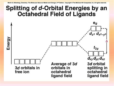
Table of Contents
Crystal Field Theory Energy Level Diagrams: A Comprehensive Guide
Crystal Field Theory (CFT) is a model used to explain the electronic structure of transition metal complexes. It focuses on the effect of the ligands (the surrounding ions or molecules) on the d-orbitals of the central metal ion. Understanding the energy level diagrams generated by CFT is crucial for predicting the magnetic properties, colors, and reactivity of these complexes. This article provides a comprehensive overview of crystal field theory energy level diagrams, exploring their construction, interpretation, and applications.
The Foundation of Crystal Field Theory
CFT simplifies the complexities of metal-ligand interactions by treating ligands as point charges that interact electrostatically with the d-orbitals of the central metal ion. These electrostatic interactions cause the degeneracy of the d-orbitals (their equal energy levels) to be lifted. The extent of this splitting depends on several factors, including the geometry of the complex and the nature of the ligands.
The Five d-Orbitals
Before exploring the splitting, let's recall the shapes and orientations of the five d-orbitals:
- d<sub>xy</sub>, d<sub>xz</sub>, d<sub>yz</sub>: These orbitals have lobes pointing between the x, y, and z axes.
- d<sub>x²−y²</sub>: This orbital has lobes pointing along the x and y axes.
- d<sub>z²</sub>: This orbital has lobes pointing along the z axis and a doughnut-shaped region in the xy plane.
These orbitals are degenerate in a free metal ion, meaning they possess the same energy level. However, the presence of ligands changes this.
Octahedral Complexes: The Most Common Geometry
Octahedral complexes are the most frequently encountered geometry in coordination chemistry. In an octahedral arrangement, six ligands surround the central metal ion, positioned along the x, y, and z axes.
Splitting of d-Orbitals in Octahedral Complexes
In an octahedral field, the electrostatic repulsion between the negatively charged ligands and the electrons in the d-orbitals is not uniform. The d<sub>x²−y²</sub> and d<sub>z²</sub> orbitals, which point directly towards the ligands, experience greater repulsion and are raised in energy. The d<sub>xy</sub>, d<sub>xz</sub>, and d<sub>yz</sub> orbitals, pointing between the ligands, experience less repulsion and are lowered in energy.
This splitting results in two energy levels:
- e<sub>g</sub> set: This higher energy level consists of the d<sub>x²−y²</sub> and d<sub>z²</sub> orbitals.
- t<sub>2g</sub> set: This lower energy level consists of the d<sub>xy</sub>, d<sub>xz</sub>, and d<sub>yz</sub> orbitals.
The energy difference between the e<sub>g</sub> and t<sub>2g</sub> sets is denoted as Δ<sub>o</sub> (or 10Dq), the octahedral crystal field splitting energy. The magnitude of Δ<sub>o</sub> determines the electronic configuration and properties of the complex.
Energy Level Diagram for Octahedral Complexes
The energy level diagram for an octahedral complex visually represents this splitting. The t<sub>2g</sub> level is shown lower than the e<sub>g</sub> level, with the energy difference clearly indicated as Δ<sub>o</sub>. The number of electrons in the d-orbitals is then filled according to Hund's rule, maximizing spin multiplicity.
(Insert a simple diagram here showing the octahedral splitting, clearly labeling t<sub>2g</sub> and e<sub>g</sub> levels and Δ<sub>o</sub>.)
Tetrahedral Complexes: A Different Perspective
Tetrahedral complexes involve four ligands surrounding the central metal ion. The splitting pattern in tetrahedral complexes differs significantly from that in octahedral complexes.
Splitting of d-Orbitals in Tetrahedral Complexes
In a tetrahedral field, the ligands are not positioned directly along the axes. The result is a smaller crystal field splitting compared to octahedral complexes. The d-orbitals split into two sets:
- e: This higher energy level consists of the d<sub>x²−y²</sub> and d<sub>z²</sub> orbitals.
- t<sub>2</sub>: This lower energy level consists of the d<sub>xy</sub>, d<sub>xz</sub>, and d<sub>yz</sub> orbitals.
The energy difference between the e and t<sub>2</sub> sets is denoted as Δ<sub>t</sub>. Importantly, Δ<sub>t</sub> ≈ (4/9)Δ<sub>o</sub>, meaning the splitting is considerably smaller in tetrahedral complexes.
Energy Level Diagram for Tetrahedral Complexes
The energy level diagram for a tetrahedral complex shows the t<sub>2</sub> level lower than the e level, with the energy difference represented by Δ<sub>t</sub>. Electron filling follows Hund's rule.
(Insert a simple diagram here showing the tetrahedral splitting, clearly labeling t<sub>2</sub> and e levels and Δ<sub>t</sub>.)
Square Planar Complexes: A Special Case
Square planar complexes have four ligands arranged in a square around the central metal ion. This geometry represents a distorted octahedral arrangement where two ligands along the z-axis are removed.
Splitting of d-Orbitals in Square Planar Complexes
The d-orbital splitting in square planar complexes is more complex than in octahedral or tetrahedral geometries. The splitting pattern results from the combined effects of the four ligands in the xy plane and the absence of ligands along the z-axis. The d<sub>x²−y²</sub> orbital experiences the greatest repulsion and is raised to the highest energy level. The d<sub>z²</sub> orbital is next highest in energy. The d<sub>xy</sub> orbital is next lowest. Then the d<sub>xz</sub> and d<sub>yz</sub> are degenerate at the lowest energy level.
Energy Level Diagram for Square Planar Complexes
The energy level diagram reflects the unique splitting pattern.
(Insert a simple diagram here showing the square planar splitting, clearly labeling all d-orbitals and their relative energy levels.)
Factors Affecting Crystal Field Splitting
Several factors influence the magnitude of the crystal field splitting energy (Δ):
-
Nature of the Ligand: Ligands are classified according to their ability to split d-orbitals. The spectrochemical series arranges ligands in order of increasing field strength: I<sup>-</sup> < Br<sup>-</sup> < S<sup>2-</sup> < SCN<sup>-</sup> < Cl<sup>-</sup> < NO<sub>3</sub><sup>-</sup> < N<sub>3</sub><sup>-</sup> < F<sup>-</sup> < OH<sup>-</sup> < C<sub>2</sub>O<sub>4</sub><sup>2-</sup> < H<sub>2</sub>O < NCS<sup>-</sup> < CH<sub>3</sub>CN < py < NH<sub>3</sub> < en < bipy < phen < NO<sub>2</sub><sup>-</sup> < PPh<sub>3</sub> < CN<sup>-</sup> < CO. Strong-field ligands produce large Δ values, while weak-field ligands produce small Δ values.
-
Oxidation State of the Metal Ion: Higher oxidation states generally lead to larger Δ values because of increased positive charge on the metal ion, resulting in stronger electrostatic interactions with the ligands.
-
Geometry of the Complex: As discussed, different geometries lead to different splitting patterns and Δ values.
Applications of Crystal Field Theory Energy Level Diagrams
Crystal field theory energy level diagrams are essential tools for understanding and predicting the properties of transition metal complexes:
-
Magnetic Properties: The electronic configuration, determined from the energy level diagram, dictates the number of unpaired electrons. This directly influences the magnetic properties of the complex (paramagnetic or diamagnetic).
-
Color: The absorption of visible light by a transition metal complex is associated with electronic transitions between the d-orbitals. The energy difference (Δ) determines the wavelength of light absorbed, thus the color of the complex. Strong-field ligands lead to large Δ, absorbing higher-energy (shorter wavelength) light and resulting in different colors compared to weak field ligands.
-
Reactivity: The electronic configuration influences the reactivity of the complex. For example, complexes with unpaired electrons may be more susceptible to oxidation-reduction reactions.
-
Spectroscopy: The study of the absorption spectra of transition metal complexes provides experimental evidence to support and refine CFT predictions.
Limitations of Crystal Field Theory
While CFT provides a useful framework for understanding the electronic structure of transition metal complexes, it has limitations:
-
Neglects Covalency: CFT treats ligands as point charges, ignoring the covalent character of metal-ligand bonds. This simplification can limit the accuracy of its predictions, especially for complexes with strong covalent interactions.
-
Oversimplified Model: The model simplifies the complex interactions between metal ions and ligands. It does not fully account for factors such as ligand-ligand interactions or the effects of π-bonding.
Beyond Crystal Field Theory: Ligand Field Theory
Ligand Field Theory (LFT) expands upon CFT by incorporating covalent interactions between the metal ion and ligands. It provides a more accurate and comprehensive description of metal-ligand bonding.
Conclusion
Crystal field theory energy level diagrams are powerful tools for understanding the electronic structure and properties of transition metal complexes. Although it has limitations, CFT provides a valuable framework for predicting magnetic properties, color, and reactivity, serving as a crucial foundation for further exploration into coordination chemistry and its applications. By understanding the principles of CFT and its limitations, we gain a deeper appreciation for the intricate world of transition metal complexes and their diverse properties. The ability to construct and interpret these diagrams is essential for any student or researcher working in the field of inorganic chemistry.
Latest Posts
Latest Posts
-
What Major Change Occurs During Metamorphism Of Limestone To Marble
Apr 01, 2025
-
Do All Living Things Respond To Stimuli
Apr 01, 2025
-
Water Boiling Physical Or Chemical Change
Apr 01, 2025
-
An Enzyme Can Only Bind One Reactant At A Time
Apr 01, 2025
-
Structures 1 2 And 3 Make Up A
Apr 01, 2025
Related Post
Thank you for visiting our website which covers about Crystal Field Theory Energy Level Diagram . We hope the information provided has been useful to you. Feel free to contact us if you have any questions or need further assistance. See you next time and don't miss to bookmark.
