How To Draw The Shear And Moment Diagrams
Muz Play
Mar 25, 2025 · 6 min read
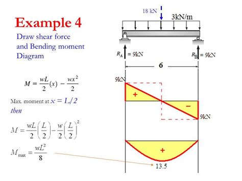
Table of Contents
How to Draw Shear and Moment Diagrams: A Comprehensive Guide
Drawing shear and moment diagrams is a fundamental skill in structural analysis. These diagrams visually represent the internal forces within a beam or structural member under various loads. Mastering this skill is crucial for engineers and students alike, as it allows for the assessment of stress levels and the safe design of structures. This comprehensive guide will walk you through the process step-by-step, covering various load types and providing practical examples.
Understanding Shear and Bending Moment
Before diving into the drawing process, let's clarify the concepts of shear force and bending moment.
Shear Force (V)
Shear force is the internal force acting parallel to the cross-section of a beam. It's a measure of how much the beam is being sheared or sliced along a particular section. Imagine cutting a beam at a specific point; the shear force represents the vertical force needed to hold the two sections together. A positive shear force indicates that the portion of the beam to the left of the section is trying to slide upwards relative to the portion to the right. A negative shear force indicates downward sliding of the left portion.
Bending Moment (M)
Bending moment is the internal resisting moment that prevents the beam from rotating under the influence of applied loads. It's a measure of the rotational effect of the forces acting on the beam. It's calculated as the sum of the moments of all forces to the left (or right) of a particular section. A positive bending moment causes compression on the top fibers and tension on the bottom fibers of the beam (like a sagging beam). A negative bending moment causes tension on the top and compression on the bottom (like a hogging beam).
Steps to Draw Shear and Moment Diagrams
The process of drawing shear and moment diagrams typically involves these steps:
-
Determine the Reactions: Begin by calculating the support reactions at the ends or supports of the beam. This involves applying equilibrium equations (ΣF<sub>x</sub> = 0, ΣF<sub>y</sub> = 0, ΣM = 0). Remember to consider all forces and moments acting on the beam.
-
Draw the Shear Diagram: Moving from left to right along the beam, calculate the shear force at various points. Remember these key points:
- At a point load: The shear force changes abruptly by the magnitude of the load. If the load is downward, the shear force decreases; if upward, it increases.
- Under a uniformly distributed load (UDL): The shear force changes linearly. The slope of the shear diagram under a UDL is equal to the magnitude of the load intensity (w).
- Under a uniformly varying load (UVL): The shear force changes parabolically.
- Points of zero shear: These points are crucial as they often correspond to the maximum or minimum bending moments.
-
Draw the Moment Diagram: Similar to the shear diagram, move from left to right along the beam and calculate the bending moment at various points. Keep these key points in mind:
- At a point load: The moment diagram changes linearly. The slope of the moment diagram at a point load is equal to the magnitude of the shear force just before or after the load.
- Under a UDL: The moment diagram changes parabolically.
- Under a UVL: The moment diagram changes cubically.
- Points of maximum moment: These points usually occur where the shear force is zero. Careful analysis is needed to locate these points precisely.
-
Label the Diagram: Clearly label all important points on the diagrams, including:
- Values of shear force and bending moment at key points.
- Locations of maximum and minimum shear force and bending moment.
- Units (kN, kNm etc.)
Practical Examples
Let's illustrate these steps with a few practical examples.
Example 1: Simply Supported Beam with a Point Load
Consider a simply supported beam of length L with a point load P acting at a distance 'a' from the left support.
-
Reactions: Using equilibrium equations, we find the reaction forces at the left (R<sub>A</sub>) and right (R<sub>B</sub>) supports:
- R<sub>A</sub> = P(L-a)/L
- R<sub>B</sub> = Pa/L
-
Shear Diagram:
- At x = 0, V = R<sub>A</sub> = P(L-a)/L
- At x = a, V = R<sub>A</sub> - P = -Pa/L
- At x = L, V = 0
The shear diagram is a straight line with a sudden drop at x = a.
- Moment Diagram:
- At x = 0, M = 0
- At x = a, M = R<sub>A</sub>a = Pa(L-a)/L
- At x = L, M = 0
The moment diagram is a triangle with a maximum value at x = a.
Example 2: Simply Supported Beam with a Uniformly Distributed Load (UDL)
Consider a simply supported beam of length L with a uniformly distributed load 'w' (force per unit length).
-
Reactions: R<sub>A</sub> = R<sub>B</sub> = wL/2
-
Shear Diagram:
- At x = 0, V = wL/2
- At x = L, V = -wL/2
The shear diagram is a straight line with a negative slope equal to 'w'.
- Moment Diagram: The moment diagram is a parabola. The maximum bending moment occurs at the midpoint (x = L/2) and is equal to wL²/8.
Example 3: Cantilever Beam with a Point Load
Consider a cantilever beam of length L with a point load P at the free end.
-
Reactions: The fixed support at the wall will have a vertical reaction force equal to P and a moment reaction equal to PL.
-
Shear Diagram: The shear diagram is a straight horizontal line at -P.
-
Moment Diagram: The moment diagram is a straight line with a slope of -P. The moment is -PL at the fixed support and 0 at the free end.
Advanced Considerations
- Overhanging beams: Beams with overhangs require careful consideration of the shear and moment diagrams, as the support reactions and internal forces can become more complex.
- Combined loads: Beams often experience multiple loads (point loads, UDL, UVL, moments). The diagrams are constructed by applying the superposition principle, combining the effects of each individual load.
- Influence lines: Influence lines can be helpful in visualizing the effect of a moving load on shear and bending moment at a specific point along a beam.
- Software tools: Various software packages (e.g., SAP2000, ETABS, etc.) can automatically generate shear and moment diagrams for complex structures.
Tips for Accurate Diagram Creation
- Neatness and organization: Clearly label axes, units, and values on your diagrams. This is crucial for clear communication and accurate interpretation.
- Sign convention: Maintain consistency in your sign convention for shear force and bending moment throughout the problem.
- Check your work: After drawing the diagrams, check your calculations and ensure that the diagrams are consistent with the equilibrium equations.
- Practice: The best way to master drawing shear and moment diagrams is through consistent practice. Work through a variety of problems, starting with simple examples and gradually increasing the complexity.
Mastering the art of drawing shear and moment diagrams is essential for structural engineers. By following these steps and understanding the underlying principles, you can accurately assess the internal forces in beams and ensure the safe and efficient design of structures. Remember, clear communication and precise calculations are paramount in this crucial aspect of structural analysis. Consistent practice will refine your skills and build confidence in your ability to accurately interpret and design structural elements.
Latest Posts
Latest Posts
-
Select All Structures Produced By Mosses
Mar 28, 2025
-
Discrepancies Between The Actual Self And The Ideal Self
Mar 28, 2025
-
When Does A Chemical Reaction Stop
Mar 28, 2025
-
What Has Definite Shapes And Definite Volumes
Mar 28, 2025
-
How To Subtract Rational Algebraic Expressions
Mar 28, 2025
Related Post
Thank you for visiting our website which covers about How To Draw The Shear And Moment Diagrams . We hope the information provided has been useful to you. Feel free to contact us if you have any questions or need further assistance. See you next time and don't miss to bookmark.
