Shear Force And Bending Moment Diagram For Cantilever Beam
Muz Play
Mar 18, 2025 · 8 min read
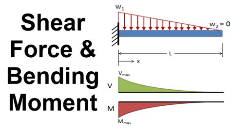
Table of Contents
Shear Force and Bending Moment Diagram for Cantilever Beam: A Comprehensive Guide
Understanding shear force and bending moment diagrams is crucial for structural engineers and anyone working with beams. These diagrams provide a visual representation of the internal forces acting within a beam under load, allowing engineers to determine the maximum stresses and design accordingly. This article focuses on cantilever beams, a common type of beam fixed at one end and free at the other, providing a detailed explanation of how to draw and interpret their shear force and bending moment diagrams.
What is a Cantilever Beam?
A cantilever beam is a structural element fixed at one end and free at the other. This fixed end provides support, resisting both vertical and horizontal forces and moments. The free end is unsupported and is subjected to the effects of applied loads. Common examples include balconies, diving boards, and overhanging parts of bridges. The unique support condition of a cantilever beam leads to characteristic shear force and bending moment distributions.
Understanding Shear Force and Bending Moment
Before diving into diagram creation, let's clarify the concepts of shear force and bending moment:
Shear Force
Shear force is the internal force acting parallel to the cross-section of the beam. It represents the force tending to cause one part of the beam to slide past the other. Imagine cutting a beam at a certain point; the shear force is the force you'd need to apply to prevent the two sections from sliding apart. It's represented by 'V'. Positive shear force is generally considered upward on the left side of the section and downward on the right side.
Bending Moment
Bending moment is the internal moment acting perpendicular to the cross-section of the beam. It represents the rotational tendency caused by forces applied to the beam. This bending moment causes the beam to bend. It's represented by 'M'. A positive bending moment causes the beam to curve upwards (creating a "sagging" effect), while a negative bending moment causes it to curve downwards (creating a "hogging" effect). In cantilever beams, a positive bending moment is generally considered as a sagging moment.
Drawing Shear Force and Bending Moment Diagrams (SFD and BMD) for Cantilever Beams: A Step-by-Step Approach
The process of drawing SFDs and BMDs for cantilever beams involves a systematic approach. Let's illustrate this with examples, breaking down the steps involved.
Example 1: A Cantilever Beam with a Point Load at the Free End
Consider a cantilever beam of length 'L' subjected to a point load 'P' at the free end.
Steps:
-
Draw the Free Body Diagram (FBD): Begin by sketching the beam with the point load clearly marked. Include the reaction forces at the fixed end (a vertical reaction force R<sub>y</sub> and a moment reaction M<sub>A</sub>).
-
Calculate Reactions: For a cantilever beam with a single point load at the free end, the vertical reaction (R<sub>y</sub>) at the fixed support is equal to the point load (P), and the moment reaction (M<sub>A</sub>) at the fixed support is equal to P*L.
-
Determine Shear Force: Start at the fixed end (where x=0). The shear force at the fixed end is equal to the reaction force R<sub>y</sub> which is P. Moving along the beam towards the free end, the shear force remains constant at 'P' until the point load is encountered. At the point load, there is a sudden change in shear force because of the point load, and from the free end to the support, the shear force is constant and equal to the point load P.
-
Determine Bending Moment: Start at the fixed end (where x=0). The bending moment at the fixed end is equal to the moment reaction M<sub>A</sub>, which is PL. As you move along the beam towards the free end, the bending moment changes linearly. At a distance 'x' from the fixed end, the bending moment is given by M = -Px. The bending moment decreases linearly from PL at the fixed end to 0 at the free end. Note that we are using the convention for positive bending moment for cantilever beams.
-
Draw the SFD and BMD: Using the calculated values, draw the shear force and bending moment diagrams. The SFD will be a horizontal line at P, and the BMD will be a straight line sloping downwards from P*L to 0.
Example 2: Cantilever Beam with a Uniformly Distributed Load (UDL)
Consider a cantilever beam of length 'L' subjected to a uniformly distributed load (UDL) of 'w' (force per unit length).
Steps:
-
Draw the FBD: Sketch the beam with the UDL acting along its length. Include the reaction forces (R<sub>y</sub> and M<sub>A</sub>) at the fixed end.
-
Calculate Reactions: For a cantilever beam with a UDL, the vertical reaction (R<sub>y</sub>) at the fixed support is equal to the total load, which is wL. The moment reaction (M<sub>A</sub>) at the fixed support is equal to (wL)L/2 = wL²/2.
-
Determine Shear Force: At the fixed end (x=0), the shear force is equal to R<sub>y</sub> (w*L). As you move towards the free end, the shear force decreases linearly. At a distance 'x' from the fixed end, the shear force is V = -wx. At the free end (x=L), the shear force is -wL.
-
Determine Bending Moment: At the fixed end (x=0), the bending moment is equal to M<sub>A</sub> (w*L²/2). As you move towards the free end, the bending moment changes parabolically. At a distance 'x' from the fixed end, the bending moment is given by M = -wx²/2. At the free end (x=L), the bending moment is -wL²/2.
-
Draw the SFD and BMD: The SFD will be a straight line sloping downwards from wL to -wL. The BMD will be a parabola starting at wL²/2 and ending at 0 at the free end.
Example 3: Cantilever Beam with Multiple Loads
When a cantilever beam is subjected to multiple loads (point loads and UDLs), the process becomes more complex but follows the same fundamental principles.
Steps:
-
Draw the FBD: Sketch the beam with all the loads and support reactions.
-
Calculate Reactions: Determine the vertical reaction (R<sub>y</sub>) and moment reaction (M<sub>A</sub>) at the fixed end by applying equilibrium equations (ΣF<sub>y</sub> = 0 and ΣM<sub>A</sub> = 0).
-
Determine Shear Force: Moving from the fixed end towards the free end, calculate the shear force at each point considering the effect of each load. Remember, point loads cause sudden changes in shear force, while UDLs cause linear changes.
-
Determine Bending Moment: Similarly, calculate the bending moment at each point along the beam. Remember that point loads cause linear changes in bending moment, while UDLs cause parabolic changes.
-
Draw the SFD and BMD: Plot the calculated values to draw the complete SFD and BMD. Pay attention to the transitions between different load segments.
Interpreting Shear Force and Bending Moment Diagrams
The SFD and BMD provide crucial information for structural design:
-
Maximum Shear Force: The location and magnitude of the maximum shear force indicate the points of maximum shear stress within the beam. This information is vital for checking shear capacity and preventing failure.
-
Maximum Bending Moment: The location and magnitude of the maximum bending moment indicate the points of maximum bending stress within the beam. This is crucial for dimensioning the beam section to resist bending stresses and prevent failure.
-
Points of Inflection: In some cases, the BMD may cross the zero axis. These points are called points of inflection, and they indicate locations where the curvature of the beam changes sign.
Significance of Shear Force and Bending Moment Diagrams in Structural Design
SFD and BMDs are essential tools in structural engineering for several reasons:
-
Design for Strength: They allow engineers to determine the maximum stresses (shear and bending) within a beam and ensure the chosen section has sufficient strength to withstand these stresses.
-
Material Selection: The diagrams help in selecting appropriate materials based on their strength and stiffness properties.
-
Beam Sizing: The diagrams aid in determining the optimal dimensions of the beam to ensure adequate strength and stiffness.
-
Failure Prediction: The diagrams help predict potential failure locations and modes.
-
Structural Optimization: By analyzing the diagrams, engineers can optimize the design of the beam for minimum weight and cost while maintaining structural integrity.
Advanced Concepts and Considerations
-
Influence Lines: For more complex loading scenarios or moving loads, influence lines can be used to determine the maximum shear force and bending moment at any given point on the beam.
-
Computer-Aided Analysis: Software packages such as ANSYS, ABAQUS, and SAP2000 are frequently employed to analyze complex structures and generate accurate shear force and bending moment diagrams.
-
Dynamic Loading: This article has focused on static loading. For dynamic loading (like vibrations), the analysis becomes considerably more complex, requiring consideration of time-varying loads and inertial effects.
This comprehensive guide provides a solid foundation for understanding shear force and bending moment diagrams for cantilever beams. Remember that practice is key to mastering this important skill. By consistently applying the methods outlined above, engineers and students can effectively analyze and design cantilever beams to ensure structural safety and efficiency.
Latest Posts
Latest Posts
-
Oxidation And Reduction Always Occur Simultaneously
Mar 18, 2025
-
General Solution For Differential Equation Complex
Mar 18, 2025
-
What Does The Zone Of Inhibition Mean
Mar 18, 2025
-
Is Water A Mixture Or Pure Substance
Mar 18, 2025
-
Which Base Is Not Found In Rna
Mar 18, 2025
Related Post
Thank you for visiting our website which covers about Shear Force And Bending Moment Diagram For Cantilever Beam . We hope the information provided has been useful to you. Feel free to contact us if you have any questions or need further assistance. See you next time and don't miss to bookmark.
