Shear Force And Bending Moment Diagrams For Cantilever Beam
Muz Play
Mar 20, 2025 · 6 min read
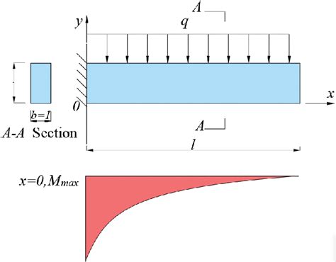
Table of Contents
Shear Force and Bending Moment Diagrams for Cantilever Beams: A Comprehensive Guide
Understanding shear force and bending moment diagrams is crucial for structural engineers and anyone involved in designing and analyzing beams. These diagrams visually represent the internal forces acting within a beam under load, providing essential information for determining stress, deflection, and overall structural integrity. This comprehensive guide will delve into the intricacies of shear force and bending moment diagrams specifically for cantilever beams, equipping you with the knowledge to confidently analyze these structures.
What is a Cantilever Beam?
A cantilever beam is a structural element fixed at one end and free at the other. This fixed end provides support, while the free end is subjected to various loads, resulting in internal forces that must be carefully considered. Examples include balconies, diving boards, and overhanging beams in buildings. The unique support condition of a cantilever beam significantly influences its shear force and bending moment diagrams.
Understanding Shear Force and Bending Moment
Before diving into the diagrams, let's define these fundamental concepts:
Shear Force
Shear force represents the internal force acting parallel to the cross-section of a beam. It's the result of the unbalanced vertical forces acting on either side of a section. Imagine slicing the beam at a point; the shear force is the force needed to keep the two sections from sliding past each other. Shear force is denoted by V.
Bending Moment
Bending moment is the internal resisting moment created within a beam due to external loads. It's the tendency of the beam to rotate about a given point. The bending moment at a section is the sum of the moments of all the forces acting on either side of the section. Bending moment is denoted by M.
Drawing Shear Force and Bending Moment Diagrams: A Step-by-Step Approach
The process of constructing these diagrams involves systematically analyzing the beam under various loading conditions. Here's a detailed step-by-step approach using a cantilever beam subjected to several common loading scenarios:
Scenario 1: Point Load at the Free End
Let's consider a cantilever beam of length L with a point load P acting at the free end.
Step 1: Calculate Reactions
For a cantilever beam with a point load at the free end, the fixed support at the wall resists both the vertical load (P) and the moment created by the load (PL).
Step 2: Determine Shear Force
- At the free end (x = 0): The shear force is equal to -P (negative because it acts downwards).
- Along the beam (0 < x ≤ L): The shear force remains constant at -P.
- At the fixed end (x = L): The shear force is still -P.
Step 3: Determine Bending Moment
- At the free end (x = 0): The bending moment is zero.
- Along the beam (0 < x ≤ L): The bending moment increases linearly from 0 to -PL (negative indicates sagging bending).
- At the fixed end (x = L): The bending moment is -PL.
Step 4: Draw the Diagrams
The shear force diagram will be a horizontal line at -P, and the bending moment diagram will be a straight line sloping downwards from 0 to -PL.
Scenario 2: Uniformly Distributed Load (UDL)
Let's consider a cantilever beam of length L with a uniformly distributed load (UDL) of w (force per unit length) along its entire length.
Step 1: Calculate Reactions
The fixed support resists a total vertical load of wL and a moment of (wL²)/2.
Step 2: Determine Shear Force
- At the free end (x = 0): The shear force is 0.
- Along the beam (0 < x ≤ L): The shear force varies linearly from 0 to -wL. The shear force at any point x is given by V = -wx.
- At the fixed end (x = L): The shear force is -wL.
Step 3: Determine Bending Moment
- At the free end (x = 0): The bending moment is 0.
- Along the beam (0 < x ≤ L): The bending moment varies parabolically. The bending moment at any point x is given by M = -(wx²)/2.
- At the fixed end (x = L): The bending moment is -(wL²)/2.
Step 4: Draw the Diagrams
The shear force diagram will be a straight line sloping downwards from 0 to -wL, and the bending moment diagram will be a parabolic curve starting at 0 and ending at -(wL²)/2.
Scenario 3: Combination of Loads
Real-world scenarios often involve multiple loads acting simultaneously. Let's consider a cantilever beam with a point load P at the free end and a UDL of w along its length.
Step 1: Calculate Reactions
The reactions at the fixed support will be the sum of the reactions due to the point load and the UDL. The vertical reaction will be P + wL, and the moment reaction will be PL + (wL²)/2.
Step 2: Determine Shear Force
The shear force will be a combination of the constant shear force from the point load and the linearly varying shear force from the UDL.
Step 3: Determine Bending Moment
The bending moment will be a combination of the linear bending moment from the point load and the parabolic bending moment from the UDL.
Step 4: Draw the Diagrams
The shear force diagram will be a straight line with a slope determined by the UDL, and the bending moment diagram will be a combination of linear and parabolic curves.
Sign Conventions
Consistent sign conventions are essential for accurate diagram construction. Common conventions include:
- Shear Force: Positive shear force indicates an upward force on the left side of the section.
- Bending Moment: Positive bending moment indicates sagging (a downward curve).
Importance of Shear Force and Bending Moment Diagrams
These diagrams are not mere visualizations; they are crucial for:
- Stress Calculation: The bending moment is directly related to bending stress, which is a primary factor in determining beam strength and failure potential.
- Deflection Analysis: Bending moment and shear force influence beam deflection, crucial for ensuring structural performance and serviceability.
- Design Optimization: Analyzing these diagrams helps engineers select appropriate beam dimensions and materials to withstand anticipated loads safely and efficiently.
- Structural Integrity Check: These diagrams help identify critical sections of the beam where stresses and bending are highest, which can inform maintenance and repair strategies.
Advanced Considerations
While this guide covers common loading scenarios, it's crucial to be aware of more complex situations:
- Overhanging beams: These have supports at multiple points and require a more detailed analysis.
- Varying cross-sections: The shear force and bending moment calculations become more complex for beams with non-uniform cross-sections.
- Dynamic loads: These include moving loads and vibrations, requiring more advanced dynamic analysis techniques.
Conclusion
Mastering the construction and interpretation of shear force and bending moment diagrams is paramount for anyone working with structural components. This guide has provided a comprehensive overview for cantilever beams, showcasing the steps involved and the significance of these diagrams in structural analysis and design. Remember to consistently apply sign conventions and to consider the complexities that can arise in real-world applications. By thoroughly understanding these concepts, you'll be well-equipped to analyze and design structures efficiently and safely.
Latest Posts
Latest Posts
-
What Is The Monomer For A Nucleic Acid
Mar 21, 2025
-
Is Melting Ice A Physical Or Chemical Change
Mar 21, 2025
-
What Are The Goals Of Science
Mar 21, 2025
-
Using Punnett Squares To Predict The Outcomes Of Crosses
Mar 21, 2025
-
Is Chemical Energy Kinetic Or Potential Energy
Mar 21, 2025
Related Post
Thank you for visiting our website which covers about Shear Force And Bending Moment Diagrams For Cantilever Beam . We hope the information provided has been useful to you. Feel free to contact us if you have any questions or need further assistance. See you next time and don't miss to bookmark.
