Shear Force Diagram Of Cantilever Beam
Muz Play
Mar 19, 2025 · 6 min read
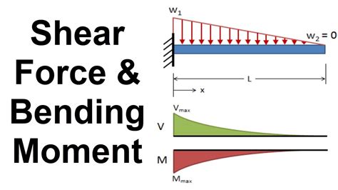
Table of Contents
Shear Force Diagram of a Cantilever Beam: A Comprehensive Guide
The cantilever beam, a structural element fixed at one end and free at the other, is a staple in engineering design. Understanding its behavior under load is crucial for ensuring structural integrity and safety. A key tool in this analysis is the shear force diagram (SFD). This comprehensive guide will delve deep into creating and interpreting shear force diagrams for cantilever beams subjected to various loading conditions. We'll cover the fundamentals, step-by-step procedures, and practical examples to solidify your understanding.
Understanding Shear Force and its Significance
Before diving into diagrams, let's define shear force. Shear force is the internal force within a beam that acts parallel to the cross-section, resisting the tendency of one part of the beam to slide past the other. It's a crucial factor in determining stress distribution and potential failure points within the beam. A well-constructed shear force diagram allows engineers to identify locations of maximum shear stress, which are critical for structural design. Understanding the shear force distribution is essential for preventing shear failures.
Constructing the Shear Force Diagram: A Step-by-Step Approach
The process of drawing a shear force diagram involves systematically analyzing the beam's internal forces at various points along its length. Here’s a structured approach:
1. Identify the Supports and Loads
Begin by clearly identifying the type of support (in this case, a fixed support at one end) and all applied loads, including their magnitudes and locations along the cantilever beam. This forms the basis of your analysis. Note that cantilever beams are typically subjected to concentrated loads (point loads), uniformly distributed loads (UDL), or a combination thereof.
2. Determine the Reactions at the Support
For a cantilever beam, the fixed support exerts both a vertical reaction force (R) and a moment (M). The vertical reaction force (R) is equal in magnitude and opposite in direction to the sum of all the vertical loads acting on the beam. This is based on the principle of static equilibrium: the sum of vertical forces must be zero.
3. Develop the Shear Force Equation
This step involves moving along the beam's length and calculating the shear force at different points. Here’s how:
-
Start at the free end: The shear force at the free end is zero.
-
Move towards the fixed end: At any point along the beam, the shear force is equal to the algebraic sum of all the vertical forces acting to the left of that point. Consider upward forces as positive and downward forces as negative.
-
Concentrated Load: When encountering a concentrated load, the shear force changes abruptly by an amount equal to the magnitude of the load. A downward load causes a negative jump in the shear force, while an upward load causes a positive jump.
-
Uniformly Distributed Load (UDL): For a UDL, the shear force changes linearly along the section under the load. The rate of change is equal to the magnitude of the UDL (force per unit length).
4. Plotting the Shear Force Diagram
Once you’ve calculated the shear force at various points along the beam, plot these values on a graph. The horizontal axis represents the length of the beam, and the vertical axis represents the shear force. Connect the points with straight lines (for concentrated loads) or straight lines with slopes determined by the UDL magnitude.
Interpreting the Shear Force Diagram
The shear force diagram provides valuable insights into the beam's behavior:
-
Maximum Shear Force: The point with the highest absolute value of shear force indicates the location of the maximum shear stress within the beam. This is a crucial design parameter as it directly relates to the beam's shear strength.
-
Points of Zero Shear: Points where the shear force is zero represent locations where bending moment is maximum. This is important for determining maximum bending stress.
-
Shape of the Diagram: The shape of the shear force diagram reveals the type and distribution of loads acting on the beam. A linear SFD suggests a concentrated load, while a linearly varying SFD indicates a uniformly distributed load.
Examples of Shear Force Diagrams for Different Loading Conditions
Let's analyze a few scenarios to illustrate the concepts.
Example 1: Cantilever Beam with a Concentrated Load at the Free End
A cantilever beam of length ‘L’ carries a concentrated load ‘P’ at its free end.
-
Reactions: R = P (upward at the fixed end).
-
Shear Force:
- At the free end (x=0): V = 0
- At any point 0 < x ≤ L: V = -P (The shear force is constant and negative along the entire beam).
Example 2: Cantilever Beam with a Uniformly Distributed Load (UDL)
A cantilever beam of length ‘L’ carries a uniformly distributed load ‘w’ (force per unit length) along its entire length.
-
Reactions: R = wL (upward at the fixed end).
-
Shear Force:
- At the free end (x=0): V = 0
- At any point x along the beam: V = -wx (The shear force varies linearly from 0 at the free end to -wL at the fixed end).
Example 3: Cantilever Beam with a Combination of Loads
Let's consider a cantilever beam with a concentrated load ‘P’ at a distance ‘a’ from the fixed end and a UDL ‘w’ along the entire length.
-
Reactions: R = P + wL
-
Shear Force:
- At the free end (x=0): V = 0
- Between 0 < x < a: V = -wx
- At x = a: V = -wa
- Between a < x ≤ L: V = -wa -P (This section shows a sudden drop because of the concentrated load).
Advanced Considerations:
-
Overhanging Beams: While this guide focuses on cantilever beams, similar principles apply to overhanging beams, requiring careful consideration of support reactions and load distribution.
-
Multiple Supports: Beams with multiple supports introduce additional complexities in reaction calculations but the fundamental principles of shear force analysis remain the same.
Practical Applications and Importance
The accurate construction and interpretation of shear force diagrams are indispensable in many engineering disciplines. They are used in:
-
Structural Design: To ensure that beams can withstand the expected loads without failure.
-
Bridge Design: For designing safe and efficient bridges.
-
Building Construction: To guarantee the stability and load-bearing capacity of buildings.
-
Aerospace Engineering: For analyzing the stress and strain in aircraft components.
Mastering the art of drawing and interpreting shear force diagrams is paramount for any engineer. This guide has provided a comprehensive foundation, equipping you with the knowledge and tools to tackle various loading scenarios on cantilever beams and beyond. By systematically following the steps outlined, you can confidently analyze the internal forces and ensure the structural integrity of your designs. Remember that practice is key to developing proficiency in this critical aspect of structural analysis.
Latest Posts
Latest Posts
-
The Permanent Party Organization Consists Of
Mar 19, 2025
-
What Elements Are Most Likely To Become Anions
Mar 19, 2025
-
In The Elderly Decreased Thyroid Function Causes
Mar 19, 2025
-
How Does The Muscular System Maintain Homeostasis
Mar 19, 2025
-
What Is Complement Of Conditional Probability
Mar 19, 2025
Related Post
Thank you for visiting our website which covers about Shear Force Diagram Of Cantilever Beam . We hope the information provided has been useful to you. Feel free to contact us if you have any questions or need further assistance. See you next time and don't miss to bookmark.
