Draw A Resonance Structure That Places A Pi Bond
Muz Play
Mar 29, 2025 · 6 min read
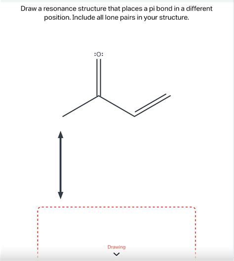
Table of Contents
Drawing Resonance Structures: Mastering the Pi Bond Placement
Resonance structures are a crucial concept in organic chemistry, representing the delocalization of electrons within a molecule. Understanding how to draw and interpret these structures is essential for predicting reactivity, stability, and molecular properties. This in-depth guide will walk you through the process of drawing resonance structures, focusing specifically on the placement of pi bonds. We will cover the fundamental rules, common examples, and advanced scenarios, ensuring you gain a thorough understanding of this important topic.
Understanding Resonance and Pi Bonds
Before diving into drawing resonance structures, let's refresh our understanding of key concepts:
What is Resonance?
Resonance describes a situation where a single Lewis structure cannot accurately represent the true distribution of electrons within a molecule. Instead, the molecule exists as a hybrid of several contributing resonance structures, each representing a possible arrangement of electrons. These structures are not real, distinct forms of the molecule but rather theoretical representations used to describe the overall electron distribution. Think of it as an average of different electron possibilities.
The Role of Pi Bonds
Pi (π) bonds are crucial in resonance structures. They are formed by the sideways overlap of p-orbitals and are weaker than sigma (σ) bonds. This weaker nature allows for the easier delocalization of electrons, a key characteristic of resonance. Pi electrons are the electrons that move between different resonance structures. The movement of these pi electrons is what creates the resonance hybrid.
Rules for Drawing Resonance Structures
Several crucial rules govern the drawing of valid resonance structures:
-
Only Move Pi Electrons and Lone Pairs: Only pi electrons (those in double or triple bonds) and lone pairs of electrons can be moved. Sigma bonds (single bonds) remain fixed.
-
Maintain the Same Atom Connectivity: The atoms must remain connected in the same arrangement. You cannot break or form sigma bonds while drawing resonance structures.
-
Maintain the Same Overall Charge: The total charge of the molecule must remain the same in all resonance structures.
-
Follow Octet Rule (Mostly): While some exceptions exist (particularly with elements beyond the second row), strive for each atom (especially carbon, nitrogen, and oxygen) to have a complete octet of electrons.
-
The More Stable, the Better Contributor: Some resonance structures contribute more significantly to the overall resonance hybrid than others. Structures with full octets, negative charges on electronegative atoms, and minimal charge separation are generally more stable and contribute more heavily to the hybrid.
-
Use Curved Arrows: Use curved arrows to illustrate the movement of electrons. The arrow's tail starts at the source of the electrons (lone pair or pi bond), and the head points to where the electrons are moving.
Examples of Drawing Resonance Structures with Pi Bond Placement
Let's work through several examples to solidify your understanding:
Example 1: Benzene
Benzene (C₆H₆) is a classic example of resonance. It has a cyclic structure with alternating single and double bonds. However, the actual structure is a hybrid of two resonance structures, each with three alternating double bonds.
(Drawings would be included here if I had image generation capabilities. Imagine two hexagons, one with double bonds in positions 1-2, 3-4, 5-6 and the other with double bonds in 2-3, 4-5, 6-1. The curved arrows showing the electron movement between the structures should be included.)
In benzene, the pi electrons are delocalized across the entire ring, resulting in exceptional stability.
Example 2: Nitrate Ion (NO₃⁻)
The nitrate ion (NO₃⁻) exhibits resonance due to the delocalization of electrons within the three nitrogen-oxygen bonds. There are three resonance structures that contribute to the overall hybrid.
(Again, image generation would be helpful here. Imagine three structures, each showing a different N=O double bond and two N-O single bonds. The negative charge would be located on the oxygen with a single bond in each structure. Curved arrows should demonstrate electron movement.)
The actual structure is an average of these three structures, resulting in equal bond lengths between nitrogen and oxygen atoms.
Example 3: Carbonate Ion (CO₃²⁻)
The carbonate ion (CO₃²⁻) is similar to the nitrate ion, showing three resonance structures with delocalized pi electrons.
(Drawings would be needed here, similar to the nitrate ion example, showing the movement of electrons and the distribution of charges.)
Like nitrate, the actual structure is a hybrid with equal carbon-oxygen bond lengths.
Example 4: Allyl Cation
The allyl cation (CH₂=CH-CH₂⁺) provides a simple example of resonance involving a positive charge.
(Again, a drawing would be beneficial here, showing the movement of the pi electrons and the relocation of the positive charge between the terminal carbons.)
The positive charge is delocalized across both terminal carbons, resulting in a more stable cation.
Example 5: Carboxylate Anion
Carboxylic acids can lose a proton to form carboxylate anions, which are stabilized by resonance.
(A drawing of a carboxylate anion, showing the delocalization of the negative charge across both oxygen atoms, and the electron movement between the resonance structures would be necessary.)
The negative charge is delocalized across both oxygen atoms, leading to increased stability.
Advanced Concepts and Considerations
Major and Minor Contributors
Not all resonance structures contribute equally to the resonance hybrid. Some structures are more stable and therefore contribute more to the overall picture. Factors affecting the relative contributions include:
-
Octet Rule Fulfillment: Structures where all atoms (especially carbon, nitrogen, and oxygen) have complete octets are more stable and contribute more significantly.
-
Formal Charge Minimization: Structures with minimal formal charges are more stable.
-
Charge Placement: Negative charges are more stable on electronegative atoms (like oxygen), and positive charges are more stable on less electronegative atoms (like carbon).
Resonance Energy
The resonance hybrid is always more stable than any individual resonance structure. This increased stability is termed resonance energy or delocalization energy. The greater the number of significant resonance structures, the higher the resonance energy, and hence, the greater the stability of the molecule.
Limitations of Resonance Theory
It's important to remember that resonance structures are just models. The actual molecule is not rapidly interconverting between different resonance structures but rather exists as a stable hybrid with an average electron distribution. The resonance hybrid structure isn't shown as one of the different resonance structures, but rather it is a blend of characteristics from each one.
Conclusion
Mastering the art of drawing resonance structures, particularly understanding the movement of pi electrons, is essential for success in organic chemistry. By following the rules and practicing with various examples, you will become proficient in predicting molecular properties and reactivity based on resonance stabilization. Remember that while the individual resonance structures are conceptual tools, the resonance hybrid they represent provides a valuable and accurate depiction of the molecule's electron distribution and overall stability. Continued practice and careful consideration of the rules outlined above will allow you to confidently tackle even the most complex resonance situations.
Latest Posts
Latest Posts
-
What Is The Specific Heat Capacity Of Aluminum
Apr 01, 2025
-
Label The Stages That Characterize Progression Of Infectious Disease
Apr 01, 2025
-
Equilibrium Solution Of A Differential Equation
Apr 01, 2025
-
How To Know If A Structure Is Polar Or Nonpolar
Apr 01, 2025
-
Does Rna Polymerase Read 3 To 5
Apr 01, 2025
Related Post
Thank you for visiting our website which covers about Draw A Resonance Structure That Places A Pi Bond . We hope the information provided has been useful to you. Feel free to contact us if you have any questions or need further assistance. See you next time and don't miss to bookmark.
