How To Calculate The Parallel Resistance
Muz Play
Mar 25, 2025 · 5 min read
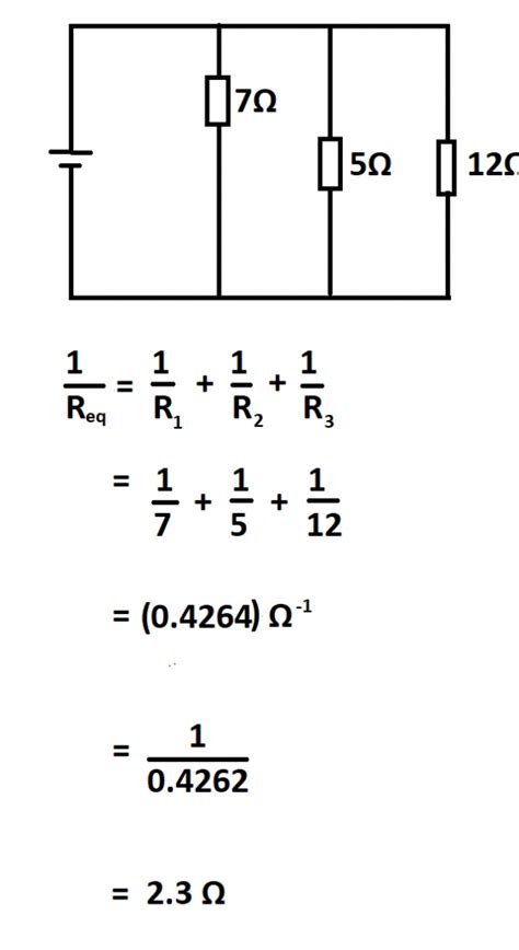
Table of Contents
How to Calculate Parallel Resistance: A Comprehensive Guide
Understanding how to calculate parallel resistance is fundamental in electronics and electrical engineering. Whether you're a seasoned professional or a curious beginner, mastering this concept is crucial for designing, troubleshooting, and analyzing circuits. This comprehensive guide will walk you through various methods, providing clear explanations and practical examples to solidify your understanding.
What is Parallel Resistance?
In a parallel circuit, multiple components, such as resistors, are connected across the same two points. This means that the voltage across each component is the same, but the current flowing through each component can differ depending on its resistance. Parallel resistance refers to the total resistance offered by the combination of these parallel components. A crucial point to remember is that the overall resistance in a parallel circuit is always less than the smallest individual resistance. This is because adding more paths for current to flow effectively reduces the overall resistance.
Methods for Calculating Parallel Resistance
Several methods exist for calculating the total resistance in a parallel circuit. We'll explore the most common ones:
1. The Reciprocal Formula (Most Common Method)
This is the most widely used and versatile method, applicable to any number of resistors in parallel. The formula is:
1/R<sub>total</sub> = 1/R<sub>1</sub> + 1/R<sub>2</sub> + 1/R<sub>3</sub> + ... + 1/R<sub>n</sub>
Where:
- R<sub>total</sub> is the total equivalent resistance.
- R<sub>1</sub>, R<sub>2</sub>, R<sub>3</sub>...R<sub>n</sub> are the individual resistances in parallel.
Example:
Let's say we have three resistors: R<sub>1</sub> = 10 ohms, R<sub>2</sub> = 20 ohms, and R<sub>3</sub> = 30 ohms, connected in parallel. To find the total resistance:
-
Calculate the reciprocal of each resistance:
- 1/10 = 0.1
- 1/20 = 0.05
- 1/30 = 0.0333
-
Add the reciprocals: 0.1 + 0.05 + 0.0333 = 0.1833
-
Take the reciprocal of the sum: 1/0.1833 ≈ 5.45 ohms
Therefore, the total resistance of the three resistors in parallel is approximately 5.45 ohms. Notice how this value is less than the smallest individual resistance (10 ohms).
2. The Product-over-Sum Formula (For Two Resistors Only)
This simplified formula is only applicable when you have exactly two resistors in parallel. The formula is:
R<sub>total</sub> = (R<sub>1</sub> * R<sub>2</sub>) / (R<sub>1</sub> + R<sub>2</sub>)
Example:
If we have two resistors: R<sub>1</sub> = 10 ohms and R<sub>2</sub> = 20 ohms, the total resistance is:
R<sub>total</sub> = (10 * 20) / (10 + 20) = 200 / 30 ≈ 6.67 ohms
This method is faster for two resistors but cannot be used for more than two.
3. The Equivalent Conductance Method
Conductance (G) is the reciprocal of resistance (R): G = 1/R. This method utilizes conductance to simplify calculations, especially with many resistors.
- Calculate the conductance of each resistor: Find the reciprocal of each resistance value.
- Sum the conductances: Add up all the individual conductances.
- Calculate the total resistance: The total resistance is the reciprocal of the total conductance.
Example (using the same three resistors as before):
-
Conductances:
- G<sub>1</sub> = 1/10 = 0.1 Siemens
- G<sub>2</sub> = 1/20 = 0.05 Siemens
- G<sub>3</sub> = 1/30 = 0.0333 Siemens
-
Total conductance: G<sub>total</sub> = 0.1 + 0.05 + 0.0333 = 0.1833 Siemens
-
Total resistance: R<sub>total</sub> = 1/0.1833 ≈ 5.45 ohms
Understanding the Implications of Parallel Resistance
The concept of parallel resistance has significant implications in circuit design and analysis:
-
Current Division: In a parallel circuit, the total current divides among the branches, with more current flowing through paths of lower resistance. This is governed by Ohm's Law (I = V/R) and Kirchhoff's Current Law (the sum of currents entering a junction equals the sum of currents leaving).
-
Voltage Consistency: The voltage across each component in a parallel circuit remains constant and equal to the source voltage.
-
Reduced Overall Resistance: As mentioned earlier, adding more resistors in parallel always reduces the total resistance of the circuit.
-
Applications in Circuits: Parallel resistance is used extensively in various electronic applications, including:
- Current Limiting: Multiple resistors in parallel can be used to limit current flow to a specific component.
- Load Sharing: Parallel resistors can distribute the load across multiple components, preventing any single component from being overloaded.
- Power Supplies: Parallel resistors might be employed to share the load in power supply circuits.
Troubleshooting Parallel Circuits
When troubleshooting parallel circuits, understanding how parallel resistance works is crucial. A lower-than-expected total resistance could indicate a short circuit, while a higher-than-expected resistance may signify an open circuit or a faulty component. Using a multimeter to measure individual resistances and the total resistance can help identify the problem.
Advanced Concepts and Considerations
-
Tolerances: Remember that resistors have tolerances (e.g., ±5%, ±1%). These tolerances can affect the accuracy of the calculated total resistance.
-
Temperature Dependence: The resistance of some components changes with temperature. This should be taken into account in high-precision applications.
-
Non-linear Resistors: The methods described above assume linear resistors (ohmic resistors). If non-linear resistors (such as diodes or transistors) are included, the calculation becomes more complex and may require more advanced techniques like iterative methods or circuit simulation software.
-
More than Three Resistors: While the reciprocal formula works perfectly well for any number of resistors, for a large number of resistors, using a spreadsheet program or specialized software for circuit analysis is often more efficient. These tools can handle complex calculations and provide more detailed circuit analysis.
Conclusion
Calculating parallel resistance is a core skill for anyone working with electrical circuits. Understanding the different methods, their applications, and the underlying principles will significantly improve your ability to design, analyze, and troubleshoot electrical systems. Mastering this fundamental concept paves the way for tackling more complex circuit analysis challenges. Remember to choose the method that best suits the number of resistors you are working with, always double-check your calculations, and consider the practical implications of tolerances and temperature effects in real-world applications. Through practice and understanding, you will become proficient in calculating parallel resistance and confident in your electrical engineering skills.
Latest Posts
Latest Posts
-
On The Weak Acid Strong Base Titration Curve
Mar 28, 2025
-
Label The Cranial Dura Septa In The Figure
Mar 28, 2025
Related Post
Thank you for visiting our website which covers about How To Calculate The Parallel Resistance . We hope the information provided has been useful to you. Feel free to contact us if you have any questions or need further assistance. See you next time and don't miss to bookmark.
