Moment Of Inertia Of Rod About End
Muz Play
Mar 27, 2025 · 6 min read
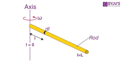
Table of Contents
Moment of Inertia of a Rod About its End: A Comprehensive Guide
The moment of inertia, a crucial concept in physics and engineering, quantifies an object's resistance to changes in its rotation. Understanding this property is vital for analyzing rotational motion, from the swing of a pendulum to the spin of a satellite. This article delves deep into calculating the moment of inertia of a rod about one of its ends, exploring different approaches and their applications.
What is Moment of Inertia?
Before we dive into the specifics of a rod, let's establish a foundational understanding of moment of inertia. It's a measure of how difficult it is to change an object's rotational speed. Unlike mass, which resists changes in linear motion, moment of inertia resists changes in angular motion. The moment of inertia depends not only on the object's mass but also on how that mass is distributed relative to the axis of rotation. The further the mass is from the axis, the greater the moment of inertia.
Mathematically, the moment of inertia (I) is defined as the sum of the products of each particle's mass (dm) and the square of its distance (r) from the axis of rotation:
I = ∫ r² dm
This integral represents the summation over all infinitesimal mass elements comprising the object. The solution to this integral depends heavily on the object's shape and the chosen axis of rotation.
Calculating the Moment of Inertia of a Rod About its End
Let's focus on a uniform rod of length 'L' and mass 'M'. We want to determine its moment of inertia (I) when the axis of rotation passes through one end of the rod.
Method 1: Integration
This method uses the fundamental definition of the moment of inertia. We consider an infinitesimal mass element 'dm' at a distance 'x' from the axis of rotation (the end of the rod).
-
Linear Mass Density: The rod is uniform, so its linear mass density (λ) is constant: λ = M/L.
-
Infinitesimal Mass Element: The mass of the infinitesimal element is dm = λ dx = (M/L) dx.
-
Integration: Substituting into the moment of inertia formula:
I = ∫₀ˡ x² dm = ∫₀ˡ x² (M/L) dx
Solving this integral gives:
I = (M/L) [x³/3]₀ˡ = (1/3)ML²
Therefore, the moment of inertia of a uniform rod about one end is (1/3)ML².
Method 2: Parallel Axis Theorem
The parallel axis theorem provides a shortcut if we already know the moment of inertia about the center of mass. The theorem states that the moment of inertia (I) about any axis parallel to an axis through the center of mass is given by:
I = I<sub>cm</sub> + Md²
Where:
- I<sub>cm</sub> is the moment of inertia about the center of mass.
- M is the total mass of the object.
- d is the distance between the two parallel axes.
For a rod, the moment of inertia about its center of mass is:
I<sub>cm</sub> = (1/12)ML²
The distance between the axis through the center of mass and the axis through one end is d = L/2. Substituting into the parallel axis theorem:
I = (1/12)ML² + M(L/2)² = (1/12)ML² + (1/4)ML² = (1/3)ML²
This confirms the result obtained through integration.
Applications of the Moment of Inertia of a Rod
Understanding the moment of inertia of a rod has numerous applications in various fields:
1. Physics and Mechanics:
-
Rotational Dynamics: Analyzing the motion of physical pendulums, compound pendulums, and other rotating systems requires knowledge of the moment of inertia. The period of oscillation, for instance, is directly influenced by the moment of inertia.
-
Angular Momentum: The angular momentum of a rotating rod is calculated as the product of its moment of inertia and angular velocity. Conservation of angular momentum is a fundamental principle in physics, and understanding moment of inertia is key to applying this principle.
-
Torque and Angular Acceleration: Newton's second law for rotation states that torque (τ) is equal to the moment of inertia multiplied by angular acceleration (α): τ = Iα. This relationship is critical for analyzing rotational dynamics problems.
2. Engineering and Design:
-
Mechanical Design: Engineers use the moment of inertia to design rotating components such as shafts, axles, and gears. Understanding how mass distribution affects rotational inertia is crucial for optimizing component strength and efficiency.
-
Structural Analysis: The moment of inertia is essential in structural analysis to determine the resistance of beams and other structural elements to bending and deformation.
-
Robotics: In robotics, the moment of inertia of robot arms and links is critical for controlling their movement and stability. Accurate calculations ensure precise and efficient robotic operation.
3. Other Disciplines:
-
Aerospace Engineering: The moment of inertia plays a crucial role in spacecraft design and attitude control. Understanding the inertia of various components is necessary for stable and controlled spacecraft maneuvers.
-
Biomechanics: In biomechanics, the moment of inertia is used to analyze the movement of limbs and the body during activities like walking, running, and jumping. This knowledge is vital for rehabilitation and performance enhancement.
Factors Affecting Moment of Inertia
Several factors significantly influence an object's moment of inertia:
-
Mass: A greater mass generally leads to a greater moment of inertia. Heavier objects are harder to rotate.
-
Mass Distribution: The distribution of mass relative to the axis of rotation is paramount. Mass concentrated further from the axis increases the moment of inertia.
-
Shape: The shape of the object significantly affects its moment of inertia. Different shapes will have different formulas for calculating I.
-
Axis of Rotation: The choice of the axis of rotation drastically affects the moment of inertia. The same object can have different moments of inertia about different axes.
Beyond the Uniform Rod: More Complex Scenarios
The calculations for a uniform rod provide a foundation for understanding moment of inertia. However, real-world objects are often more complex. For non-uniform rods or objects with irregular shapes, numerical methods like finite element analysis are often necessary. These techniques divide the object into small elements, calculate the moment of inertia of each element, and then sum them to find the total moment of inertia.
Conclusion
The moment of inertia of a rod about its end, (1/3)ML², is a fundamental result in physics and engineering. This article explored two methods for deriving this value – integration and the parallel axis theorem – and highlighted its numerous applications across diverse fields. Understanding the moment of inertia is essential for analyzing rotational motion and designing efficient and stable systems. While the uniform rod provides a simplified model, the principles discussed here lay the groundwork for tackling more complex scenarios and solidifying a strong grasp of this critical concept. Remember that precise calculations are vital in many engineering applications, so utilizing appropriate tools and methods is key to accuracy.
Latest Posts
Latest Posts
-
How Does Fermentation Allow Glycolysis To Continue
Mar 30, 2025
-
Which Subatomic Particle Carries A Positive Charge
Mar 30, 2025
-
Signs A Chemical Reaction Has Occurred
Mar 30, 2025
-
Duties Of An Agent In Law
Mar 30, 2025
-
What Is The Symbol For Population Variance
Mar 30, 2025
Related Post
Thank you for visiting our website which covers about Moment Of Inertia Of Rod About End . We hope the information provided has been useful to you. Feel free to contact us if you have any questions or need further assistance. See you next time and don't miss to bookmark.
