Shear Force And Bending Moment Cantilever Beam
Muz Play
Mar 24, 2025 · 6 min read
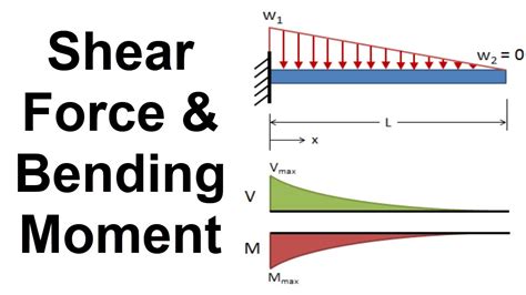
Table of Contents
Shear Force and Bending Moment in Cantilever Beams: A Comprehensive Guide
Cantilever beams, characterized by their fixed end and free end, are fundamental structural elements found in numerous engineering applications. Understanding the distribution of shear force and bending moment along these beams is crucial for ensuring structural integrity and safety. This comprehensive guide delves into the intricacies of shear force and bending moment in cantilever beams, providing a detailed explanation, practical examples, and insights into their significance in structural analysis.
Understanding Shear Force and Bending Moment
Before we delve into the specifics of cantilever beams, let's establish a clear understanding of shear force and bending moment. These are internal forces and moments that develop within a beam in response to external loads.
Shear Force (V)
Shear force represents the internal force acting parallel to the cross-section of the beam. It's a measure of how much the beam resists the tendency to slide or shear along a particular section. A positive shear force is typically defined as one that causes the beam to shear upwards on the left side of the section.
Bending Moment (M)
The bending moment is the internal moment acting perpendicular to the cross-section of the beam. It measures the beam's resistance to bending or rotation. A positive bending moment is typically defined as one that causes compression on the top surface and tension on the bottom surface of the beam.
Analyzing Shear Force and Bending Moment in Cantilever Beams
Let's consider a simple cantilever beam of length 'L' subjected to a point load 'P' at its free end. We'll analyze the shear force and bending moment diagrams step by step.
Step 1: Free Body Diagram (FBD)
The first step in analyzing any structural element is to draw a clear free body diagram. This diagram represents the beam, the supports, and all the external loads acting on it. For our cantilever beam with a point load 'P' at the free end, the FBD will show a reaction force and reaction moment at the fixed end.
Step 2: Shear Force Diagram (SFD)
To draw the shear force diagram (SFD), we'll analyze the shear force at different points along the beam. For a cantilever beam with a single point load at the free end:
- At the free end (x = 0): The shear force is equal to the point load, V = -P (negative since it acts downwards).
- At the fixed end (x = L): The shear force is equal to the reaction force at the fixed end, V = P (positive since it acts upwards).
The SFD will be a straight line connecting these two points. The shear force remains constant between the load and the fixed support.
Step 3: Bending Moment Diagram (BMD)
To draw the bending moment diagram (BMD), we'll calculate the bending moment at various points along the beam. For our example:
- At the free end (x = 0): The bending moment is zero, M = 0.
- At the fixed end (x = L): The bending moment is maximum and is equal to the product of the load and the length of the beam, M = PL (positive since it causes compression at the top and tension at the bottom).
The BMD will be a linear function of x, increasing linearly from zero at the free end to a maximum value of PL at the fixed end. This is because the shear force is constant between the fixed end and the free end.
Influence of Different Loading Conditions
The shear force and bending moment diagrams significantly vary depending on the type and distribution of the applied load. Let's examine a few scenarios:
1. Uniformly Distributed Load (UDL)
A uniformly distributed load (UDL) is a load spread evenly across the length of the beam. For a cantilever beam with a UDL of 'w' (force per unit length):
- Shear Force: The shear force varies linearly from -wL at the free end to 0 at the fixed end.
- Bending Moment: The bending moment varies parabolically, reaching a maximum value of -wL²/2 at the fixed end.
2. Multiple Point Loads
With multiple point loads, the shear force changes abruptly at each load location. The bending moment changes linearly between loads, with the slope equal to the shear force.
3. Combination of Loads
Real-world scenarios often involve a combination of point loads and uniformly distributed loads. In these cases, you need to superimpose the effects of each load type to obtain the overall shear force and bending moment diagrams. This involves calculating the shear force and bending moment due to each load separately and then adding them algebraically.
Significance of Shear Force and Bending Moment Diagrams
These diagrams are crucial for several reasons:
-
Design: They are fundamental in structural design, allowing engineers to determine the maximum shear force and bending moment experienced by the beam. This information is critical for selecting appropriate materials and cross-sectional dimensions to ensure the beam can withstand the expected loads without failure. Understanding the maximum bending moment is essential for calculating stresses and deflections.
-
Failure Prediction: The diagrams help predict potential failure points. Locations with high shear force or bending moment are more prone to failure, so extra attention needs to be paid during the design phase.
-
Material Selection: The diagrams inform the selection of appropriate materials and cross-sectional shapes that can effectively resist the internal forces and moments.
-
Structural Analysis: They're used for refined structural analysis, assisting in determining deflections, stresses, and overall structural behavior. Software tools often utilize these diagrams as inputs for more complex analyses.
Advanced Considerations
-
Sign Convention: Consistent sign conventions are essential for accurate interpretation of the diagrams. Positive shear force is generally defined as upwards on the left side of the section, while positive bending moment causes compression at the top and tension at the bottom.
-
Influence Lines: For more complex scenarios, influence lines can be used to determine the shear force and bending moment at a specific point due to a moving load.
Practical Applications
Cantilever beams with varying load conditions are commonly found in many structures and engineering applications:
-
Building Structures: Overhanging balconies, cantilevered roofs, and some bridge designs.
-
Aircraft Wings: The wings of aircraft can be simplified as cantilever beams supporting aerodynamic forces.
-
Machine Components: Many machine components like levers, brackets, and arms are cantilevered beams.
-
Signs and Billboards: Cantilever structures are frequently used to support signage, especially those located away from the buildings.
-
Bridges: Some bridge designs incorporate cantilever spans.
Conclusion
Understanding the behavior of shear force and bending moment in cantilever beams is fundamental for any engineer or designer working with structural elements. By mastering the concepts outlined in this guide, you'll be better equipped to analyze, design, and ensure the structural integrity of cantilever beams in a wide range of applications. Remember that careful consideration of different loading conditions and the use of appropriate design codes are vital for ensuring the safe and efficient use of cantilever beam structures. Regularly reviewing and practicing these principles will improve your understanding and ability to confidently work with this crucial structural element.
Latest Posts
Latest Posts
-
Did The Swahili Coast Require Monsoons To Access
Mar 25, 2025
-
An Irreversible Inhibitor Is One That
Mar 25, 2025
-
When Elements Combine To Form Compounds
Mar 25, 2025
-
Describe The Sampling Distribution Of P Hat
Mar 25, 2025
-
How To Determine State Of Matter In Chemical Equation
Mar 25, 2025
Related Post
Thank you for visiting our website which covers about Shear Force And Bending Moment Cantilever Beam . We hope the information provided has been useful to you. Feel free to contact us if you have any questions or need further assistance. See you next time and don't miss to bookmark.
