Draw The Shear And Moment Diagrams For The Cantilever Beam
Muz Play
Mar 30, 2025 · 6 min read
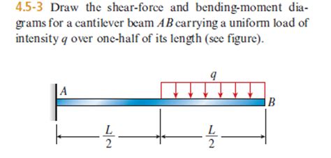
Table of Contents
Draw the Shear and Moment Diagrams for a Cantilever Beam: A Comprehensive Guide
Drawing accurate shear and moment diagrams is crucial for structural engineers and designers. These diagrams visually represent the internal forces within a beam under load, enabling engineers to assess stress levels and ensure structural integrity. This comprehensive guide will walk you through the process of drawing shear and moment diagrams specifically for cantilever beams, a common structural element. We'll cover various loading scenarios, provide step-by-step instructions, and offer tips for accuracy.
Understanding Cantilever Beams
A cantilever beam is a structural member fixed at one end and free at the other. This fixed end provides support against both rotation and translation, while the free end is unrestrained. The unique characteristics of cantilever beams lead to specific patterns in their shear and moment diagrams. These beams are frequently encountered in structures such as balconies, diving boards, and overhanging building sections.
Key Concepts: Shear Force and Bending Moment
Before diving into diagram creation, let's briefly review fundamental concepts:
-
Shear Force (V): The internal force acting parallel to the cross-section of the beam. It represents the tendency of one section of the beam to slide past the other. Shear force is calculated by summing the vertical forces to the left (or right) of a section. A positive shear force indicates an upward force on the left section.
-
Bending Moment (M): The internal moment acting perpendicular to the cross-section of the beam. It represents the tendency of the beam to bend or rotate. Bending moment is calculated by summing the moments of forces to the left (or right) of a section. A positive bending moment causes compression at the top and tension at the bottom.
Steps to Draw Shear and Moment Diagrams
The process involves several steps and understanding the sign conventions is crucial for accuracy. We will cover a variety of loading scenarios.
1. Point Load (Concentrated Load)
Consider a cantilever beam of length L subjected to a point load P at the free end.
Steps:
-
Support Reactions: The fixed end will experience a reaction force (R) equal to P in the upward direction and a reaction moment (M<sub>R</sub>) equal to P*L in the counter-clockwise direction.
-
Shear Force Diagram:
- Moving from the fixed end towards the free end, the shear force starts at -P (due to the reaction force).
- It remains constant at -P until the free end is reached.
- The shear force diagram is a horizontal line at -P.
-
Bending Moment Diagram:
- The bending moment starts at the fixed end at +P*L (due to the reaction moment).
- It decreases linearly as we move towards the free end.
- At the free end, the bending moment is zero.
- The bending moment diagram is a straight line with a negative slope.
2. Uniformly Distributed Load (UDL)
Consider a cantilever beam of length L subjected to a uniformly distributed load (w) along its entire length.
Steps:
-
Support Reactions: The fixed end will experience a reaction force (R) equal to wL (upward) and a reaction moment (M<sub>R</sub>) equal to (wL*L)/2 = wL²/2 (counter-clockwise).
-
Shear Force Diagram:
- The shear force starts at -w*L at the fixed end.
- It increases linearly towards the free end.
- At the free end, the shear force is zero.
- The shear force diagram is a straight line with a positive slope.
-
Bending Moment Diagram:
- The bending moment starts at +wL²/2 at the fixed end.
- It decreases parabolically towards the free end, reaching zero at the free end.
- The bending moment diagram is a parabola.
3. Triangular Load
A cantilever beam subjected to a triangular load, increasing linearly from zero at the fixed end to w at the free end, presents a slightly more complex scenario.
Steps:
-
Support Reactions: The total load is (wL)/2, so the reaction force (R) at the fixed end is (wL)/2 (upward). The reaction moment (M<sub>R</sub>) is (wLL)/6 = wL²/6 (counter-clockwise).
-
Shear Force Diagram:
- Starts at -(w*L)/2 at the fixed end.
- Varies parabolically, reaching zero at the free end.
-
Bending Moment Diagram:
- Starts at +wL²/6 at the fixed end.
- Varies cubically, reaching zero at the free end.
4. Combined Loading
Real-world scenarios often involve combined loading – a mix of point loads, UDLs, and triangular loads. To handle this:
- Determine support reactions: Sum the vertical forces and moments to find the reactions at the fixed support.
- Shear Force Diagram: Calculate the shear force at various points along the beam by considering all loads to the left of each point. The shear force will change abruptly at point loads and linearly under UDLs and parabolically under triangular loads.
- Bending Moment Diagram: Calculate the bending moment at various points using the shear force and applying the relationship that the slope of the moment diagram equals the shear force.
Tips for Accurate Diagram Creation
- Sign Conventions: Strictly adhere to consistent sign conventions. Using a consistent sign convention is crucial to prevent errors. A common convention is positive shear force causing upward deflection on the left side of a section, and positive bending moment causing compression at the top of the beam.
- Use clear labelling: Clearly label the axes, units, significant points (e.g., maximum shear, maximum moment), and values.
- Check your calculations: Carefully check your calculations of support reactions and values at critical points.
- Utilize software: Software packages are available to assist with the calculations and automated generation of these diagrams. They are helpful for complex loading scenarios, offering valuable time savings and enhanced accuracy.
Importance of Shear and Moment Diagrams
Understanding and accurately constructing shear and moment diagrams is essential for several reasons:
-
Structural Design: The diagrams provide crucial information to assess the stresses within the beam, enabling engineers to select appropriate materials and dimensions to ensure the beam can safely withstand the applied loads. The maximum bending moment is crucial in determining the beam's flexural strength. The maximum shear force is vital for verifying the shear strength.
-
Failure Prediction: The diagrams help predict potential failure points, based on whether the maximum bending moment or shear force exceed the allowable stresses of the material.
-
Optimizing Designs: The diagrams allow for optimization of the beam's design and size to minimize material usage while maintaining structural integrity.
-
Troubleshooting: When investigating structural issues, shear and moment diagrams are critical in determining the causes of failure or unexpected behavior.
Conclusion
Drawing shear and moment diagrams for cantilever beams is a fundamental skill in structural engineering. Understanding the underlying principles and systematically following the steps outlined above will enable you to accurately represent the internal forces and moments within the beam. Remember to consistently apply sign conventions and thoroughly check your calculations. With practice, you'll develop proficiency in this essential engineering skill. The ability to accurately interpret these diagrams is critical for ensuring the safety and efficiency of structural designs. Combining this skill with modern structural analysis software will help create robust and safe structures.
Latest Posts
Latest Posts
-
Which Electrons Are Involved In Chemical Bonding
Apr 01, 2025
-
How Do You Calculate Stream Gradient
Apr 01, 2025
-
What Happens To A Cell In A Hypertonic Solution
Apr 01, 2025
-
Titration Of Fruit Juice Lab Answers
Apr 01, 2025
-
Electric Field Lines About A Point Charge Extend
Apr 01, 2025
Related Post
Thank you for visiting our website which covers about Draw The Shear And Moment Diagrams For The Cantilever Beam . We hope the information provided has been useful to you. Feel free to contact us if you have any questions or need further assistance. See you next time and don't miss to bookmark.
