Moment Of Inertia Of A Rod About Its End
Muz Play
Mar 26, 2025 · 6 min read
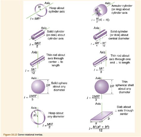
Table of Contents
Moment of Inertia of a Rod About Its End: A Comprehensive Guide
The moment of inertia, a crucial concept in physics and engineering, quantifies an object's resistance to changes in its rotation. Understanding this property is vital for analyzing rotational motion, from the swing of a pendulum to the spin of a satellite. This article delves deep into calculating the moment of inertia of a rod about its end, exploring various methods and their applications. We'll cover the fundamental principles, the derivation of the formula, and practical examples to solidify your understanding.
Understanding Moment of Inertia
Before diving into the specifics of a rod, let's establish a firm grasp of the concept itself. The moment of inertia (often denoted as I) isn't a single value but rather depends on the object's mass distribution and the axis of rotation. Intuitively, it represents how "difficult" it is to change an object's rotational speed. A higher moment of inertia means more resistance to angular acceleration.
Think of it like this: it's easier to spin a pencil than a baseball bat, even if they weigh the same. This difference stems from their mass distribution relative to the axis of rotation. The baseball bat's mass is concentrated further from the axis, increasing its resistance to spinning—its higher moment of inertia.
The Formula and its Components
The general formula for calculating the moment of inertia is:
I = ∫ r² dm
Where:
- I represents the moment of inertia.
- r is the perpendicular distance of a small mass element (dm) from the axis of rotation.
- dm is an infinitesimally small mass element of the object.
- ∫ denotes integration, summing up the contributions of all the mass elements.
This integral highlights the importance of mass distribution. Masses farther from the axis contribute more significantly to the total moment of inertia.
Deriving the Moment of Inertia of a Rod About its End
Now, let's focus on our specific case: a thin, uniform rod rotating about one of its ends. We'll use the general formula and calculus to derive the expression.
1. Defining Parameters:
Let's consider a rod of total length L and total mass M. We'll assume the rod is uniform, meaning its mass is evenly distributed along its length. We'll place the axis of rotation at one end of the rod.
2. Setting up the Integral:
We can divide the rod into infinitesimally small segments of length dx. Since the rod is uniform, the mass of each segment (dm) is proportional to its length:
dm = (M/L) dx
The distance r of each segment from the axis of rotation is simply x, where x is the distance from the end of the rod.
3. Performing the Integration:
Now we can substitute these expressions into our general formula:
I = ∫ r² dm = ∫₀ˡ x² (M/L) dx
This integral is straightforward to solve:
I = (M/L) ∫₀ˡ x² dx = (M/L) [x³/3]₀ˡ = (M/L) (L³/3) = (1/3) ML²
Therefore, the moment of inertia of a uniform rod about one end is:
I = (1/3) ML²
Understanding the Result and its Implications
The derived formula, I = (1/3)ML², reveals several key insights:
-
Direct Proportionality to Mass (M): As the mass of the rod increases, so does its moment of inertia. A heavier rod resists changes in rotation more strongly.
-
Squared Proportionality to Length (L²): The length of the rod has a more significant impact. Doubling the length quadruples the moment of inertia. This is because increasing the length increases the distance of the majority of the mass from the rotation axis, significantly amplifying the resistance to rotation.
-
Axis of Rotation is Crucial: The moment of inertia is highly dependent on the chosen axis of rotation. If the rod were to rotate about its center, the moment of inertia would be different (specifically, (1/12)ML²).
Applications of the Moment of Inertia Formula
The formula for the moment of inertia of a rod about its end finds widespread applications in various fields:
-
Mechanical Engineering: Designing rotating machinery, like gears, shafts, and flywheels, requires precise calculations of moment of inertia to predict their behavior under different loads and speeds. Understanding the resistance to rotational acceleration is crucial for designing safe and efficient systems.
-
Robotics: Robots often involve complex linkages and rotating components. Accurate moment of inertia calculations are essential for modeling the robot's dynamics, controlling its movements, and optimizing its performance.
-
Aerospace Engineering: Designing aircraft and spacecraft involves careful consideration of rotational dynamics. The moment of inertia of various components, including wings, control surfaces, and propellers, influences their maneuverability and stability.
-
Physics Experiments: Many physics experiments, particularly those involving rotational motion, utilize rods as a fundamental component. The moment of inertia is a crucial parameter in analyzing the motion and extracting meaningful results.
Parallel Axis Theorem: Expanding the Possibilities
The parallel axis theorem provides a powerful tool for calculating the moment of inertia about an axis that is parallel to an axis through the center of mass. This theorem states:
I = I<sub>cm</sub> + Md²
Where:
- I is the moment of inertia about the parallel axis.
- I<sub>cm</sub> is the moment of inertia about the axis through the center of mass.
- M is the total mass of the object.
- d is the perpendicular distance between the two parallel axes.
For our rod example, we know I<sub>cm</sub> = (1/12)ML². Using the parallel axis theorem, we can easily re-derive the moment of inertia about one end (where d = L/2):
I = (1/12)ML² + M(L/2)² = (1/3)ML²
This confirms our previous result and demonstrates the power of the parallel axis theorem in simplifying calculations.
Beyond the Ideal Rod: Real-World Considerations
While our derivation assumed a perfectly uniform, thin rod, real-world rods might exhibit variations:
-
Non-uniform Density: If the rod's density isn't constant, the integral becomes more complex, requiring a density function to accurately describe the mass distribution.
-
Non-negligible Thickness: For thicker rods, the moment of inertia calculation would need to account for the distribution of mass across the rod's cross-section. This often involves more complex integration or the use of approximation techniques.
-
Material Properties: The material's elasticity and stiffness can influence rotational behavior, especially under significant loads or high speeds.
Conclusion: Mastering the Moment of Inertia
The moment of inertia of a rod about its end, (1/3)ML², is a fundamental concept in rotational dynamics with widespread applications. Understanding its derivation, implications, and the parallel axis theorem empowers you to analyze and predict the behavior of rotating systems, from simple pendulums to complex engineering designs. Remember that this formula provides a solid foundation for further explorations into more complex scenarios, always keeping in mind the importance of accurate mass distribution modeling for precise calculations. By mastering this crucial concept, you'll gain valuable insight into the fascinating world of rotational mechanics.
Latest Posts
Latest Posts
-
Isotopes Have A Different Number Of
Mar 27, 2025
-
What Are Blocks In The Periodic Table
Mar 27, 2025
-
How Can You Identify A Metamorphic Rock
Mar 27, 2025
-
Chemical Properties Of Alkali Metals And Alkaline Earth Metals
Mar 27, 2025
-
Does Increasing Temperature Increase Reaction Rate
Mar 27, 2025
Related Post
Thank you for visiting our website which covers about Moment Of Inertia Of A Rod About Its End . We hope the information provided has been useful to you. Feel free to contact us if you have any questions or need further assistance. See you next time and don't miss to bookmark.
