Draw The Shear And Moment Diagram
Muz Play
Mar 23, 2025 · 7 min read
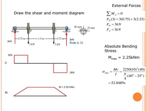
Table of Contents
Drawing Shear and Moment Diagrams: A Comprehensive Guide
Drawing shear and moment diagrams is a crucial skill for any civil or mechanical engineer. These diagrams provide a visual representation of the internal forces within a structural member, allowing engineers to assess stress levels and ensure structural integrity. This comprehensive guide will walk you through the process step-by-step, covering various load types and providing helpful tips and tricks to master this essential engineering skill.
Understanding Shear and Bending Moment
Before diving into the drawing process, let's solidify our understanding of shear and bending moment.
Shear Force
Shear force is the internal force acting parallel to a cross-section of a structural member. It represents the transverse force resisting the tendency of one part of the member to slide past the other. Think of cutting a beam in half; the shear force is the force needed to prevent the two halves from slipping. Shear forces are crucial in considering the shear stress and potential failure in a structural member.
Bending Moment
The bending moment is the internal resisting moment acting on a cross-section of a structural member. It arises from the bending action of the applied loads, causing the member to deform into a curved shape. The bending moment is responsible for bending stresses within the material, and its magnitude is a key factor in determining the member's structural capacity. A larger bending moment implies a greater risk of failure due to bending.
Steps to Draw Shear and Moment Diagrams
The process involves several key steps, regardless of the complexity of the loading:
Step 1: Determine the Reactions
Before drawing the diagrams, you must determine the reactions at the supports. This involves applying the equations of equilibrium (ΣFx = 0, ΣFy = 0, ΣM = 0). For statically determinate beams, this can be done relatively easily. Statically indeterminate beams require more advanced techniques. Accurate reaction calculations are fundamental—any error here will propagate through the entire analysis.
Example: Consider a simply supported beam with a uniformly distributed load (UDL). The reactions at each support can be calculated by summing the vertical forces and the moments about a chosen support.
Step 2: Draw the Shear Force Diagram (SFD)
The shear force at any point along the beam is the algebraic sum of the vertical forces to the left (or right) of that point. Remember to follow sign conventions consistently: upward forces are typically positive, and downward forces are negative.
-
Concentrated Loads: A concentrated load causes a sudden change in the shear force. The magnitude of the change is equal to the load itself.
-
Uniformly Distributed Loads (UDL): A UDL produces a linear variation in the shear force. The slope of the shear force diagram is equal to the intensity of the UDL.
-
Triangular Loads: Triangular loads result in a parabolic variation in the shear force.
Plotting the SFD: Start at one support and move along the beam, adding or subtracting forces as you encounter them. The resulting diagram will show the shear force variation along the beam's length. Points of zero shear are particularly important as they often correspond to locations of maximum bending moment.
Step 3: Draw the Bending Moment Diagram (BMD)
The bending moment at any point along the beam is the algebraic sum of the moments of all forces to the left (or right) of that point. The bending moment is calculated by integrating the shear force. This integration corresponds to the area under the SFD.
-
Constant Shear: A constant shear force between two points produces a linearly varying bending moment. The slope of the BMD is equal to the shear force.
-
Linearly Varying Shear: A linearly varying shear force between two points produces a parabolically varying bending moment.
-
Parabolic Shear: This will lead to a cubic variation of the bending moment.
Plotting the BMD: Start at a support where the bending moment is typically zero (unless there’s a moment reaction) and move along the beam, calculating the moment at each section using the area under the SFD. The sign convention for bending moments should be consistent; clockwise moments are often considered negative, while counterclockwise moments are positive. Points of maximum bending moment are crucial for assessing the structural safety of the beam.
Different Types of Loads and Their Impact on Diagrams
The shape of the shear and moment diagrams greatly depends on the type of loads acting on the beam:
1. Concentrated Loads
A concentrated load (point load) causes a step change in the shear force diagram and a linear change in the bending moment diagram. The magnitude of the step change in the SFD equals the load magnitude.
2. Uniformly Distributed Loads (UDL)
A UDL causes a linear change in the shear force diagram and a parabolic change in the bending moment diagram. The slope of the SFD is equal to the intensity of the UDL.
3. Triangular Loads
A triangular load causes a parabolic change in the shear force diagram and a cubic change in the bending moment diagram. The equations for the shear and moment become more complex to calculate.
4. Combined Loads
Real-world scenarios often involve a combination of load types. In these cases, the diagrams are constructed by superposing the individual effects of each load type. This requires careful attention to sign conventions and accurate summation of forces and moments.
Tips and Tricks for Accurate Diagram Drawing
-
Consistent Sign Convention: Use a consistent sign convention for forces and moments throughout the entire process to avoid errors.
-
Check for Equilibrium: After drawing the diagrams, always verify that the reactions calculated in Step 1 are consistent with the areas under the shear force diagram.
-
Use Software: Engineering software can significantly simplify the process of drawing shear and moment diagrams, especially for complex loading scenarios. This software will allow for quicker calculations and ensure greater accuracy.
-
Break Down Complex Beams: If the beam has multiple segments or complex loading, break it down into simpler sections and analyze each section individually. Then, combine the results to create the complete shear and moment diagrams.
-
Identify Critical Points: Pay close attention to points where the shear force is zero or changes sign. These are critical points often corresponding to points of maximum bending moment.
-
Neat and Organized Drawings: Create clear and well-organized diagrams. Labeling all key points, values, and axes is essential for understanding.
Advanced Concepts and Applications
The principles discussed here form the foundation for analyzing more complex structural systems. These include:
-
Statically Indeterminate Beams: These beams have more supports than necessary to satisfy equilibrium equations. Advanced techniques, such as the method of superposition or the force method, are required to analyze these structures.
-
Frames and Trusses: The concept of shear and moment diagrams extends to more complex structures such as frames and trusses, but the process becomes more involved.
-
Influence Lines: Influence lines illustrate how the shear force and bending moment at a specific point change as a unit load moves across the beam. This is critical for live load analysis.
-
Finite Element Analysis (FEA): FEA offers a powerful numerical method for analyzing complex structures and loading conditions beyond the capabilities of hand calculations.
Conclusion
Mastering the ability to draw shear and moment diagrams is an essential skill for structural engineers. It provides an invaluable tool for assessing internal forces and predicting the potential failure of structural members. While the basic concepts are relatively straightforward, accurate calculations and a clear understanding of load types are vital for generating reliable results. By following the steps outlined in this guide, along with consistent practice and attention to detail, you can confidently draw accurate shear and moment diagrams, and efficiently progress in your structural engineering studies. Remember that practice is key – work through many examples to build your intuition and proficiency. This will allow you to swiftly tackle even the most complex structural analysis problems.
Latest Posts
Latest Posts
-
Electric Field Of A Uniformly Charged Disk
Mar 25, 2025
-
Chi Square Test For Association Calculator
Mar 25, 2025
-
An Ion Has Unequal Numbers Of
Mar 25, 2025
-
Calculate Average Atomic Mass Of Isotopes
Mar 25, 2025
-
Understanding Theoretical Actual And Percent Yield
Mar 25, 2025
Related Post
Thank you for visiting our website which covers about Draw The Shear And Moment Diagram . We hope the information provided has been useful to you. Feel free to contact us if you have any questions or need further assistance. See you next time and don't miss to bookmark.
