Transfer Function Of An Rc Circuit
Muz Play
Mar 25, 2025 · 6 min read
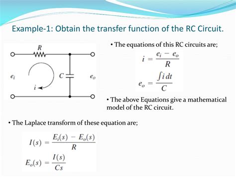
Table of Contents
Understanding the Transfer Function of an RC Circuit
The RC circuit, a fundamental building block in electronics, consists of a resistor (R) and a capacitor (C) connected in series or parallel. Its simplicity belies its importance; it forms the basis for many crucial applications, from filtering signals to timing circuits. A deep understanding of its transfer function is therefore essential for any electronics engineer. This article will delve into the intricacies of the RC circuit's transfer function, exploring its derivation, analysis, and practical applications.
What is a Transfer Function?
Before diving into the specifics of the RC circuit, let's establish a clear understanding of the transfer function. In essence, a transfer function is a mathematical representation of a system's output in relation to its input. It describes how a system modifies or transforms an input signal. For linear time-invariant (LTI) systems, like our RC circuit, this relationship is typically expressed in the Laplace domain (s-domain) using complex frequency (s). The transfer function, often denoted as H(s), is the ratio of the output to the input in the s-domain:
H(s) = V<sub>out</sub>(s) / V<sub>in</sub>(s)
Where:
- V<sub>out</sub>(s) is the Laplace transform of the output voltage.
- V<sub>in</sub>(s) is the Laplace transform of the input voltage.
This function provides crucial information about the system's behavior, including its frequency response, stability, and transient response.
Deriving the Transfer Function of a Series RC Circuit
Let's consider a series RC circuit with a voltage source (V<sub>in</sub>) connected across the resistor and capacitor. Applying Kirchhoff's voltage law (KVL), we get:
V<sub>in</sub>(t) = V<sub>R</sub>(t) + V<sub>C</sub>(t)
Where:
- V<sub>in</sub>(t) is the input voltage as a function of time.
- V<sub>R</sub>(t) is the voltage across the resistor.
- V<sub>C</sub>(t) is the voltage across the capacitor.
Using the constitutive relationships for resistors and capacitors:
- V<sub>R</sub>(t) = R * i(t) (Ohm's Law)
- i(t) = C * (dV<sub>C</sub>(t)/dt) (Capacitor Current)
We can substitute these into the KVL equation:
V<sub>in</sub>(t) = R * C * (dV<sub>C</sub>(t)/dt) + V<sub>C</sub>(t)
Now, we take the Laplace transform of this equation, keeping in mind the properties of Laplace transforms:
- L{dV<sub>C</sub>(t)/dt} = sV<sub>C</sub>(s) - V<sub>C</sub>(0) (Initial condition)
- L{V<sub>in</sub>(t)} = V<sub>in</sub>(s)
- L{V<sub>C</sub>(t)} = V<sub>C</sub>(s)
Assuming zero initial conditions (V<sub>C</sub>(0) = 0), the equation in the s-domain becomes:
V<sub>in</sub>(s) = RCsV<sub>C</sub>(s) + V<sub>C</sub>(s)
Our output voltage is V<sub>C</sub>(s), so we can rearrange the equation to solve for the transfer function:
H(s) = V<sub>C</sub>(s) / V<sub>in</sub>(s) = 1 / (1 + RCs)
This is the transfer function of a series RC circuit. Notice that it's a first-order system, characterized by a single pole at s = -1/(RC).
Analyzing the Transfer Function
The transfer function provides valuable insights into the circuit's behavior:
Pole and Time Constant:
The pole at s = -1/(RC) determines the circuit's time constant (τ):
τ = RC
The time constant represents the time it takes for the capacitor voltage to reach approximately 63.2% of its final value during a step response. A larger time constant indicates a slower response.
Frequency Response:
To understand the frequency response, we substitute s with jω, where ω is the angular frequency (ω = 2πf, where f is the frequency):
H(jω) = 1 / (1 + jωRC)
The magnitude response is:
|H(jω)| = 1 / √(1 + (ωRC)²)
And the phase response is:
∠H(jω) = -arctan(ωRC)
This reveals that the RC circuit acts as a low-pass filter. At low frequencies (ωRC << 1), the magnitude is approximately 1, and the phase is close to 0. At high frequencies (ωRC >> 1), the magnitude decreases inversely proportional to frequency, and the phase approaches -90 degrees. The cutoff frequency (f<sub>c</sub>), where the magnitude response is reduced to 1/√2 (approximately -3dB), is:
f<sub>c</sub> = 1 / (2πRC)
Step Response:
The step response describes the circuit's output when the input is a sudden step voltage. It can be obtained by taking the inverse Laplace transform of H(s) multiplied by the Laplace transform of a step function (1/s):
V<sub>C</sub>(t) = 1 - e<sup>-t/RC</sup>
This shows an exponential rise in the capacitor voltage, approaching its final value (equal to the input voltage) asymptotically with a time constant τ = RC.
Parallel RC Circuit Transfer Function
The derivation for a parallel RC circuit is slightly different. Here, the output voltage is across the capacitor, which is the same as the input voltage. The current splits between the resistor and capacitor. Using similar techniques involving KCL (Kirchhoff's Current Law) and Laplace transforms, the transfer function for the output voltage across the capacitor can be derived as:
H(s) = V<sub>C</sub>(s) / V<sub>in</sub>(s) = 1 / (1 + 1/(RCs)) = RCs / (1 + RCs)
This represents a high-pass filter. Notice that at low frequencies, the magnitude is small and approaches zero. At high frequencies, the magnitude approaches one, confirming its high-pass filtering behavior.
Applications of RC Circuits
The versatility of RC circuits makes them indispensable in numerous applications:
-
Filtering: As demonstrated, RC circuits can act as low-pass or high-pass filters, crucial for removing unwanted frequencies from signals. They are used extensively in audio equipment, power supplies, and communication systems.
-
Timing Circuits: The predictable exponential charging and discharging characteristics of the capacitor are leveraged in timing circuits. These circuits are found in oscillators, timers, and pulse-width modulation (PWM) systems.
-
Coupling and Decoupling: RC circuits act as coupling circuits to pass AC signals while blocking DC signals, or as decoupling circuits to isolate different parts of a circuit from unwanted noise.
-
Differentiators and Integrators: With specific component values and operational amplifier configurations, RC circuits can perform differentiation or integration of signals. This finds applications in signal processing.
Advanced Considerations
While this discussion focuses on simple RC circuits, real-world scenarios involve more complex considerations:
-
Non-ideal components: Real resistors and capacitors exhibit parasitic effects such as inductance and capacitance, affecting the circuit's performance at higher frequencies.
-
Temperature effects: The values of resistors and capacitors are temperature-dependent, impacting the circuit's characteristics over a range of temperatures.
-
Nonlinear behavior: Under certain conditions, particularly at high voltages or currents, the components might exhibit non-linear behavior, deviating from the ideal model.
Conclusion
The transfer function of an RC circuit provides a powerful tool for understanding and analyzing its behavior. By understanding its derivation, frequency response, and time-domain characteristics, engineers can effectively utilize RC circuits in a wide array of applications. Remember that while idealized models offer a strong foundation, practical implementations require consideration of non-ideal components and environmental factors to ensure reliable and robust performance. This comprehensive understanding allows for efficient design and optimization in various electronic systems. Further exploration of more complex circuits built upon the foundation of the RC circuit will unlock even more sophisticated functionalities. Mastering the RC circuit's transfer function is a crucial stepping stone towards a deeper grasp of electrical engineering principles.
Latest Posts
Latest Posts
-
What Are The Building Blocks For Fats
Mar 28, 2025
-
The Si Unit Of Energy Is The
Mar 28, 2025
-
Water Molecules Move Across Cells By
Mar 28, 2025
-
Is Ammonium Hydroxide A Strong Base
Mar 28, 2025
-
What Is The Activity Series In Chemistry
Mar 28, 2025
Related Post
Thank you for visiting our website which covers about Transfer Function Of An Rc Circuit . We hope the information provided has been useful to you. Feel free to contact us if you have any questions or need further assistance. See you next time and don't miss to bookmark.
